www.masterweld.co.uk
Copper and alloys
The most important factor is the high rate of heat conductivity of
copper, making preheating of heavy sections necessary to give
proper fusion of weld and base metal.
Types of electrodes
Arc welding electrodes are classified into a number of groups
depending on their applications. There are a great number of
electrodes used for specialised industrial purposes which are not of
particular interest for everyday general work. These include some
low hydrogen types for high tensile steel, cellulose types for welding
large diameter pipes, etc. The range of electrodes dealt with in this
publication will cover the vast majority of applications likely to be
encountered; are all easy to use and all will work on even the most
basic of welding machines.
Metals Being Joined and
Electrode Comments
Mild steel
6013 ideal electrodes for all general-purpose work. Features include
outstanding operator appeal, easy arc starting and low spatter.
Mild steel
7014 all positional electrode for use on mild and galvanised steel
furniture, plates, fences, gates, pipes and tanks etc. Especially
suitable for vertical down welding.
Cast iron
99% nickel suitable for joining all cast irons except white cast iron
Stainless steel
318l-16 high corrosion resistance. Ideal for dairy work, etc.
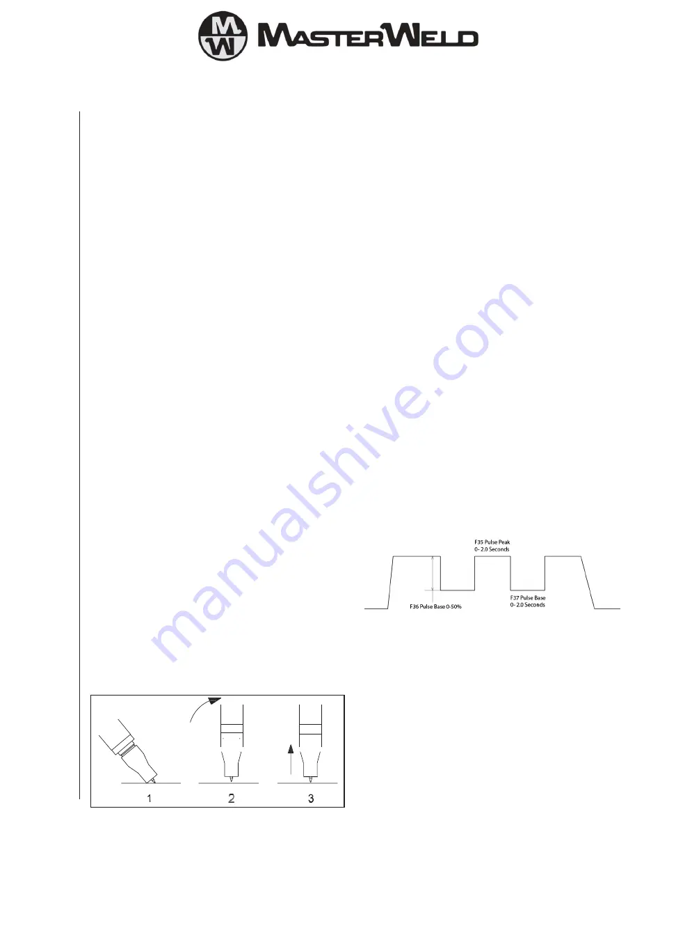
On stainless steels vertical, lift the torch up from the work piece to
draw out an arc. To prevent melting of the end of the tungsten so this
in a smooth rapid movement
TIG welding guide ranges.
6.8 Basic TIG Welding Guide
TIG welding cable connection
Connect the TIG torch to the - terminal and the work lead to the +
terminal for direct current straight polarity. Direct current straight
polarity is the most widely used polarity for DC TIG welding. It allows
limited wear of the electrode since 70% of the heat is concentrated
at the work piece. Connect the gas hose on the TIG torch to the gas
outlet on the gas regulator. Move the selector switch on the front
panel of the machine to the LIFT-TIG position.
Torch starting in LIFT-TIG mode
To operate in TIG welding mode select JOB 6 on the right control
and the left display will show amperage and the right display will
show TIG. You can adjust the welding amperage with the left control.
Ensure the gas supply is switched on and gas is flowing from the
front of the torch nozzle. Briefly contact the tip of the tungsten
electrode down onto the work piece with the torch at around 70º
from vertical, lift the torch up from the work piece to draw out an arc.
To prevent melting of the end of the tungsten so this in a smooth rapid
movement.
6.9 Additional Functions
6.9.1 Memory function
RAPID panel has 3 memory location available which can be
selected using button 5
PRO panel has up to 100 memory locations available. The number
of memory locations available to the use can be set.
Auto save is enabled by default and after adjusting any of the
parameters the memory display will flash to show it is saved.
Altering the number of memory locations available (PRO panel).
Press and hold the F button for 5 seconds. Select F45 and increase
or decrease the number of memory locations to suit the user.
Switching off Auto Save. Press and hold the F button for 5 seconds.
Select F44 and set the value to zero. With auto save off it is now
required to press and hold the down button (5) until the memory
display goes out which confirms the save. You can switch on
Auto save again by setting the value of F44 to 01.
6.9.2 Supervisor Lock
It is possible to set the machine in lock mode so that the operator
can only use JOBs that have been saved to memory. To activate the
lock function first program the machine as required for the user and
then follow the following steps to activate the lock.
Switch off the machine press the mem down arrow (5) and hold
while switching on the machine until you see LOC on the display
and then rotate the right hand knob so the value is 01 (On). It will
now not be possible to adjust any parameter other than the memory
location and the voltage trim.
To remove the lock switch off the machine press the mem down
arrow (5) and hold while switching on the machine until you see
LOC on the display and then rotate the right hand knob so the value
is 00 (Off).
6.9.3 Pulse Balance Adjustment
The standard preset double pulse function should be suitable for all
applications but if you need to change the double pulse parameter
you can do so as detailed below
Using the F functions F35, F36, F37 and F38
F35 is the time spent and the peak (normal) power level and can be
adjusted from 0 to 2.0 Seconds. Increasing this parameter will give
increased heat input and a wider spread of the weld pool.
F36 is the difference between the normal power level and the low
power level. It can be adjusted from 0 to 50% at 50% the low power
level will be 50% less than the normal power level.
F37 is the time spent and the base (low) power level and can be
adjusted from 0 to 2.0 Seconds. Increasing this parameter will give
reduced heat input
F38 is the voltage trim for the base current level and can be adjusted
+/- 0 to 9.9 volts
14


