background image

EN / CZone Touch 10 User Guide


18


           Tel:  +64 9 415 7261, [email protected], www.bepmarine.com 

3.2.3 

Monitoring 

The main menu’s Monitoring tab accesses all configured metering on the CZone network. 


Depending on which CZone modules are on the vessel, you may have one or more of the following five 
monitoring types: 


DC Monitoring

 - 12V or 24V supplies such as house or starter batteries, and chargers 


AC Monitoring

 - 120V or 230V AC sources, such as shore power supplies, on-board generators and 

inverters 


Tanks


– levels for tanks such as fresh-water, fuel, black water or grey water 


Alarms

 - Alarm history, and unacknowledged alarms at four severity levels: Warning, Standard, 

Important and Critical 


Systems in Operation

 - access to all configured circuits that are active, in the same categories that 

appear under the Control menu. 

There may also be a Favourites category which will be configured by the boatbuilder for fast access to essential 
meters. 


Figure 5 

Monitoring Home-page for a Typical Vessel 

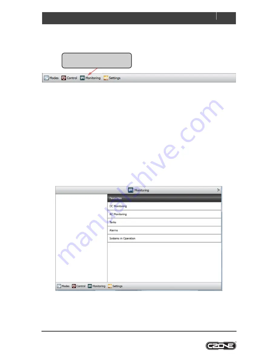
Click Monitoring on the main menu 
along the bottom of the screen. 

Содержание CZone Touch 10

Страница 1: ...Touch 10 User Guide v1 0 1 ...

Страница 2: ... is a difference between a translation of this manual and the English version the English version should be considered the official version FCC Statement This device complies with the limits for a Class B digital device pursuant to part 15 of FCC rules These rules pertain to reasonable protection from harmful interference in a normal installation This equipment generates extremely low levels of ra...

Страница 3: ...unctions by Group 10 3 2 1 Modes 10 3 2 2 Control 12 3 2 2 1 DC Control and AC Control Circuits 13 3 2 2 2 AC Mains Control 14 3 2 2 3 Inverter Charger Control 16 3 2 3 Monitoring 18 3 2 3 1 DC Monitoring 19 3 2 3 2 AC Monitoring 20 3 2 3 3 Tanks 21 3 2 3 4 Alarms 22 3 2 3 5 Systems in Operation 25 3 2 4 Settings 26 3 2 4 1 About and Updating Touch 10 s Software 26 3 2 4 2 Network 28 3 2 4 3 Dipsw...

Страница 4: ... bepmarine com Table of Figures Figure 1 Touch 10 s Tab based Main Menu 8 Figure 2 Home page for the Monitoring Functional Group 8 Figure 3 Control Home page for a Typical Vessel 12 Figure 4 DC Control the Lights Category 13 Figure 5 Monitoring Home page for a Typical Vessel 18 ...

Страница 5: ...nd has no moving parts With its large touch screen and multiple levels of backlighting Touch 10 provides fast and positive operation in all visibility conditions Together with toughened glass and splash proofing this makes it ideal for cockpits and other exposed locations 1 2 Dimensions 1 3 Connections 1 USB 2 0 2 Ethernet 3 GPIO General Purpose Input Output 4 NMEA 2000 5 8 32V DC power 199 7 13 1...

Страница 6: ...k requires a unique dipswitch to operate correctly and the Touch 10 has a virtual dipswitch Refer to the CZone Configuration Tool manual for this process 1 Turn on the circuit breaker or switch supplying power to the Touch 10 2 The CZone splash screen will appear for about 10 seconds then the text Starting Configuration Claim Touch 10 will now read the CZone configuration file from another CZone d...

Страница 7: ...Touch 10 can see the rest of the CZone devices go to the Settings Network page and check configured modules are showing Online 7 Update software on Touch 10 if a newer version is available Current software version can be checked by selecting About from the Settings page Refer to Chapter 3 2 4 1 on Page 26 for software update process 8 Touch 10 is now ready for use ...

Страница 8: ...ers alarms and others 4 Settings control over Touch 10 and CZone parameters rather than other on board equipment This includes units of measurement backlight settings time zones etc Touch 10 offers a tab based main menu with a home tab for each of the above functional groups The menu is shown in Figure 1 It is displayed along the bottom of the screen at all times except when a keypad overlay is sh...

Страница 9: ... blank unless used by the current function e g to mimic meters for monitoring D Sub categories available for further selection In this example clicking the Accept button will drill down further into the highlighted Favourites sub category E Tab based main menu ...

Страница 10: ...and are configured by the boatbuilder The Modes home page appears listing all available operating modes that have been configured for the vessel The topmost mode is highlighted The following is an example screen showing how to change modes 1 Click Modes on the main menu along the bottom of the screen The current mode has a tick beside it 3 Click On to confirm the mode change The tick moves to the ...

Страница 11: ...ow is an example which summarises the effect that selecting a mode has on the vessel s systems The boatbuilder should supply a similar summary for each of the modes configured for a particular vessel Modes Configuration Systems On Day Cruise Night Cruise Systems Off Backlight Zone 1 On On On 30 0 Off Cabin Lights On Off On 2 0 Off Charger Not Used Not Used Not Used Not Used Courtesy Lights Blue Of...

Страница 12: ...Control a page for controlling monitoring AC mains supplies e g generator and or shore power Note Requires a CZone AC Mains Interface Inverters Chargers a page for controlling monitoring Mastervolt Inverter Chargers All AC and DC circuit types are accessible through the All circuit category Circuits may also be assigned a group category such as Lights or Pumps which allows circuits on large system...

Страница 13: ...d On Time displays the aggregate time for which the circuit has been active Faults reports the most recent fault raised by the circuit or None if it is operating correctly E The status bars are dark while the circuit is inactive When an on off circuit is active these indicators change to The example circuit is dimmable so the number of lit segments in each status bar tracks the circuit s setting W...

Страница 14: ... vessel The example below is typical the ship is in an operating mode which routes AC mains automatically depending on the priorities of any available sources A Current draw and power consumption are tracked for the selected source B Voltage and frequency are tracked even if the source is unloaded C Sources including the Parallel circuit breaker are coloured green when connected to load groups D C...

Страница 15: ...lue when they are available but unloaded or black when they are unavailable The following screen shows how to override generator control and supply the load groups from a different AC mains source 1 Highlight an alternative source Here only Shore Power 1 is available 3 The load groups disconnect from the previous source and are supplied from the selected source instead 6 The display pane tracks th...

Страница 16: ...ay an example is shown below On choosing Inverters Chargers from the Control home page the available inverters and chargers are listed A The name of the selected charger or inverter is shown in the display pane B The charger status is shown On or Off 1 Click to highlight the inverter or charger that you wish to control 2 Use the buttons to turn charging on or off D A C F E B ...

Страница 17: ... Bulk Absorption or Float D The charging circuit is represented using current paths and icons for the battery and for AC DC conversion E The state of the source is shown RMS voltage current drain frequency and real power F The battery s charging state is shown DC voltage and input current ...

Страница 18: ... sources such as shore power supplies on board generators and inverters Tanks levels for tanks such as fresh water fuel black water or grey water Alarms Alarm history and unacknowledged alarms at four severity levels Warning Standard Important and Critical Systems in Operation access to all configured circuits that are active in the same categories that appear under the Control menu There may also...

Страница 19: ... the voltage C The calculated remaining capacity is shown in amp hours D The calculated charge state is shown as a percentage of full charge and as the green portion of a small icon resembling a cell E The maximum and minimum recent states of the battery are reported Click on the DC device that you wish to monitor Highlighting shifts to the selected device and the display pane tracks its status B ...

Страница 20: ... meter gauge C The RMS voltage of the selected AC Mains source is shown also in the highlighted region and using an analogue meter gauge D The frequency of the AC Mains source is shown E The real power being supplied to all load groups supplied by the source is shown F Worst case recent performance of the selected source is shown including maximum and minimum RMS voltages maximum current draw by a...

Страница 21: ...rted in the highlighted section as a percentage and as the blue portion of a status bar C In the display pane a cylindrical tank mimic shows the tank level in blue and as a percentage D The capacity of the tank is shown in the configured units Click on the tank that you wish to monitor In this example only the Fresh Water Tank is configured The selected tank is highlighted and the display pane tra...

Страница 22: ... alarm severities and their behaviour Alarm Level Bell Colour Action on Trigger Additional Note Critical Red Full Screen Dialog Audible Tone Acknowledgement times out after 10 minutes then re alarms Important Orange Full Screen Dialog Audible Tone Acknowledgement times out after 10 minutes Standard Yellow Full Screen Dialog Full screen dialogue disappears once alarm is acknowledged Warning Blue Be...

Страница 23: ... B The name of the input that raised the alarm is shown in the display pane C The name of the alarm is displayed D The CZone module that detected the alarm is shown E The alarm state is shown either Enabled or Acknowledged F The alarm severity is described in words and with a bell shaped icon of the appropriate colour A B C D F E Click the Acknowledge button to disable an alarm if its state is Ena...

Страница 24: ...erity saved in history can be changed from the Settings System Alarm Log Severity page A The alarm severity is indicated with a bell shaped icon of the appropriate colour B The name of the input that raised the alarm is displayed C The name of the alarm is shown D The CZone module that detected the alarm is shown E The severity of the alarm is reported in words F The date time stamps for the alarm...

Страница 25: ... Pumps Fans Ventilation and Lighting Selecting any category displays all active circuits in that category alternatively selecting All displays all active circuits regardless of their category Systems in operation behave exactly as DC or AC Control circuits selecting a circuit displays its status and allows the circuit to be controlled Consult Figure 4 for an example ...

Страница 26: ...uch 10 and CZone settings B The software and library versions show what is installed on Touch 10 C Touch 10 s dipswitch affects how it is addressed on the CZone network If necessary this can be changed via the System settings D This field shows the name of the CZone network s current configuration This also can be changed via System 1 Click Settings on the main menu along the bottom of the screen ...

Страница 27: ...s of splash screens is displayed this takes a minute or so 3 The update ends with Touch 10 at its configured Startup Screen typically the Modes home page 4 The Update Software dialogue appears Use the up and down buttons to browse for the software package 5 To quit at any time click the Cancel button 6 Click the Accept button to install the replacement software package ...

Страница 28: ...ch the current configuration C The display pane tracks the highlighted module D The type of the module is displayed Touch 10 is a CZone Display Interface E The module s configured name is displayed F The configured dipswitch setting for the module is displayed Note If this differs from the module s actual dipswitch setting the module will show as Offline G The status of the module is repeated in t...

Страница 29: ...etting This will occur if for example the owner has a hardware dipswitch The owner s name is in green if its dipswitch setting could be claimed without causing a conflict This will occur if for example the owner s dipswitch can be reassigned in software B The configured dipswitch setting is displayed Each switch is on if its digit is 1 or off it is digit is 0 1 Click Dipswitch on the Settings Syst...

Страница 30: ...diagnostics 3 2 4 4 1 Read Configuration from CZone If you click to accept Read from the dialogue Touch 10 will first read the current CZone configuration then load it leaving its configuration synchronized with the rest of the network You may see screens in the following sequence some very briefly and others lasting several seconds Starting configuration claim Receiving Configuration progress per...

Страница 31: ...rest of the CZone network synchronized to the same configuration If a USB drive is inserted in addition to the Current Configuration described above you can use the up and down buttons to browse any configuration zcf files on the drive The configuration you choose will be loaded and written first to Touch 10 and then to the rest of the network leaving all modules synchronized 3 2 4 4 3 Save Config...

Страница 32: ... 2 Resolution 1280 x 800 pixels WXGA Aspect Ratio Widescreen 16 10 Backlight LED Colour 18 bit RGB CPU Freescale ARM Cortex A8 1GHz Memory SDRAM 1GB DDR Flash 4GB eMMC Peripherals Battery backed real time clock Power Supply 8 32VDC Power Consumption 1A 12V 500mA 24V Ingress Protection IP66 Operating Temperature 0 C 50 C Storage Temperature 20 C 60 C Interfaces NMEA 2000 USB 2 0 10 100Mbps Ethernet...

Страница 33: ...To which this declaration related is in conformity with the following standards or other normative documents EMC EN 60945 2002 IEC 60529 2013 ES150602012SE 1 ES150602013E 1 ES1506030453E 1 FCC Part15 2015 Subpart B Class B FCC ANSI C63 4 2009 And therefore conforms with the protection requirements of Council Directives 2004 108 EC relating to electromagnetic compatibility Albany New Zealand 18 Sep...

Отзывы: