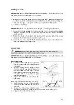
Bevel adjustment
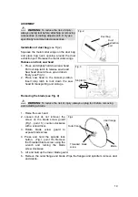
Fig.6
1. When a bevel cut is required, loosen the
bevel lock (Fig.1 point 26) by turning it
counter-clockwise.
2. Tilt the saw head to the desired angle as
shown on the bevel scale. The blade can
be positioned at any angle, from a 90°
straight cut (0° on the scale) to a 45° left
bevel. (See Fig. 6)
3. Tighten the bevel lock to secure the saw
head.
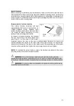
Change the laser line batteries
WARNING:
Unplug the compound
mitre saw before making any adjustments.
Failure to unplug the saw could result in
accidental starting causing possible serious personal injury.
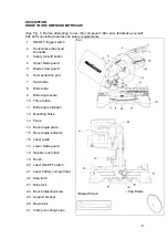
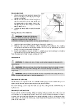
1. Open the laser line battery compartment. (See Fig1; point 21.)
2. Remove the two old batteries. When replacing the batteries, the battery
compartment should be thoroughly cleaned. Use a soft, dry paintbrush or similar
brush, to remove all sawdust and debris.
3. Insert new batteries; ensure c/- polarity (see mark stamped on battery
compartment). Secure the battery cover in position.
Note: Replacement “AAA” require a rating of 1.5V
OPERATION
WARNING:
To reduce the risk of injury, wear safety goggles or glasses with
side shields.
WARNING:
Before each use, check that the blade is free from cracks; loosen
teeth, missing teeth, or any other damage. Do not use if damage is noticed or
suspected.
WARNING
: Always wait for the blade to stop completely and unplug the tool
before changing accessories or making adjustment.
Movement of mitre saw
Lift the mitre saw only when the saw is OFF and the plug is removed from the power
supply outlet and the saw head is locked in the down position.
To avoid damage, never carry the mitre saw by the cutting handle. ALWAYS carry it
by the base.
Mounting of the mitre saw
To prevent the tool from sliding, falling or tipping during operation, the mitre saw can
be mounted to a supporting surface such as a level, sturdy worktable or bench.
Position the mitre saw and workbench to allow adequate room for crosscutting long
work pieces. To mount the mitre saw, insert fasteners through the four holes in the
base of the mitre saw.
Bevel angle
indicator
12
Содержание 55-6857-6
Страница 17: ...17 ...


