


4
1
2
3
OPERATING INSTRUCTIONS
OPERATING INSTRUCTIONS
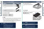
FILLING RESERVOIR WATER (Fig. 10)
Before cutting, the water reservoir must be filled with
water.
•
Remove the bevel table.
•
Fill the water reservoir with clean tap water to above the
tip of arrow (the Min. fill line (16)).
•
Replace the bevel table.
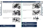
CHANGING RESERVOIR WATER (Fig. 11)
•
Unplug the saw.
•
Remove the bevel table.
•
Remove the overflow drain (18) and empty waste water
into a bucket. DO NOT allow the water to splash onto the
ground or around the machine.
•
Rinse the machine thoroughly.
•
Discard the waste water in accordance with local
regulations.
•
Replace with clean water.
•
Replace the bevel table.
25
24
NOTE:
The overflow drain prevents overfilling.
NOTE:
Make sure there is no debris inside the water level component compartment.
Fig. 10
Fig. 11
7
12
7
29
18
16
7
1
7
11
WARNING!
• Do not add chemicals or detergents to the water.
• During use, the water level must never drop below the MIN water fill line.
WARNING!
• ALWAYS put the tile saw on a clean, stable and flat surface.
• Maintain an adequate distance from the cutting wheel when cutting.
•
Do not reach into the working range of the spinning cutting wheel while the
product is operating.
•
Carefully check the workpiece to be machined. There must not be objects,
such as utility lines, nearby that will present a hazard while working.
•
The product is not suitable for cutting materials such as marble, fine stoneware
and granite. Tile floor made up of these materials must not be cut.
•
Wait until the cutting wheel has reached its maximum speed before commencing
work.
•
Before commencing work, check there is sufficient cooling water in the product.
•
In the case of complex cuts (mitre or bevel cuts) we recommend making a test
cut beforehand.
• The cutting wheel will continue to rotate for a few seconds after the machine
has been switched off. Wait for the cutting wheel to stop before removing the
workpiece or making any adjustments.
model no. 055-6789-8 | contact us 1-800-689-9928
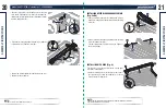
WANGING!
To avoid damage to the teeth on the rip fence
and fixing base, DO NOT slide the rip fence on
the working table when assembly or using.
Fig. 12
Fig. 13
USING RIP GUIDE (Fig. 12)
•
Open the locking levers (7) (located on the two ends of
the rip guide (1)).
• Remove the rip guide (1).
•
Replace the rip guide (1) to the desired position.
•
Push down the locking levers (7).
USING MITRE GUIDE (Fig. 13)
To adjust angles:
• Loosen the mitre knob (12).
•
Rotate to the desired angle by moving the guide (29) on
the mitre guide (11) left or right.
•
Tighten the mitre knob (12) securely before turning on
the saw.
MAKING CUTS