background image

37

TM

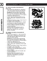
Procedure B (Fig. 29, 31)

•  Slightly turn the laser horizontal 

adjustment knob (2) to adjust the 

horizontal angle of the laser beam on the 

top of the board. If the laser beam is out 

of parallel from left to right, turn the laser 

horizontal adjustment knob (2) clockwise; 

If the laser beam is out of parallel from

  right to left, turn the laser horizontal 

adjustment knob (2) counter-clockwise 

until the laser beam is parallel with the 

horizontal “pattern line.”

•  Recheck the laser beam alignment.

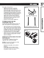
EXTENSION WING USE AND 

ADJUSTMENT (Fig. 32)

The left and right side extension wings can 

offer extra support for long workpieces.

•  Lift the locking lever (1) and pull out the 

left extension wing to the desired support 

length. Push down on the locking lever (1) 

to tighten the extension wing. Repeat for 

the right side extension wing if needed.

•  If the locking lever (1) will not tighten, 

adjust the nut (2), located under the base, 

1/4 turn clockwise using a 3/8" (10 mm) 

wrench until tight.

REPETITIVE CUTTING USING THE STOP 

PLATE (Fig. 32)

The stop plate is designed for making 

repetitive cuts of the same length.

NOTE:

 Use only one stop plate at a time, 

NEVER use both stop plates.

•  Rotate the stop plate (3) to vertical 

position.

•  If stop plate will not rotate, loosen 

the locking screw (4) 1/4 turn using a 

screwdriver and 8 mm wrench.

Fig. 31

Laser beam

Pattern line

Counter-clockwise Clockwise

Fig. 32

1

4

3

2

AD

JUS

TMENT

S

Содержание 055-6767-0

Страница 1: ...1 TM IMPORTANT Please read this manual carefully before using this mitre saw and save it for reference Model no 055 6767 0 INSTRUCTION MANUAL TM Dual beveling Sliding Compound Mitre Saw with Laser Line ...

Страница 2: ...model no 055 6767 0 contact us 1 800 689 9928 2 ...

Страница 3: ...afety and operating instructions Read all instructions and follow them with use of this products TABLE OF CONTENTS QUICK START GUIDE 4 SYMBOLS 6 SPECIFICATIONS 7 SAFETY GUIDELINES 8 ACCESSORIES AND ATTACHMENTS 15 TOOLS NEEDED FOR ASSEMBLY 17 CARTON CONTENTS 18 KNOW YOUR SLIDING MITRE SAW 19 ASSEMBLY 21 ADJUSTMENTS 29 OPERATION 38 MAINTENANCE 55 TROUBLESHOOTING GUIDE 58 REPLACEMENT PARTS 60 WARRANT...

Страница 4: ...TE The blade has been installed in the mitre saw at the factory Recheck and adjust the alignment of the blade before cutting if necessary 1 Place hands at least 7 1 2 19 cm away from the path of the blade out of the no hands zone 2 7 1 2 19 cm 7 1 2 19 cm Use the hold down clamp to hold the workpiece firmly against the fence to prevent movement towards the blade It is safer than using your hand an...

Страница 5: ... saw blade down to the workpiece to see the cutting path of the blade Then squeeze trigger switch to start the saw and lower the blade into the workpiece with a firm downward motion 5 Hold the cutting arm in the down position Release the trigger switch and wait for all moving parts to stop before moving your hands and raising the cutting arm 6 QUICK START GUIDE TM ...

Страница 6: ...STAND INSTRUCTION MANUAL To reduce the risk of injury user and all bystanders must read and understand instruction manual before using this product SUPPORT AND CLAMP WORK KEEP HANDS AWAY FROM BLADE Failure to keep your hands away from the blade will result in serious personal injury WEAR RESPIRATORY AND HEARING PROTECTION Always wear respiratory and hearing protection DANGER WARNING CAUTION DANGER...

Страница 7: ...ht 0 47 Left BEVEL POSITIVE STOPS 0 33 9 45 Right Left CUTTING CAPACITY CROSSCUT MAXIMUM HEIGHT 3 1 2 x 11 1 2 8 9 x 29 2 cm CROSSCUT MAXIMUM WIDTH 3 1 2 x 12 1 2 8 9 x 31 8 cm MITRE 45 RIGHT LEFT 3 1 2 x 8 3 4 8 9 x 22 2 cm BEVEL 45 RIGHT 1 x 12 1 2 2 5 x 31 8 cm BEVEL 45 LEFT 1 5 8 x 12 1 2 4 1 x 31 8 cm 45 MITRE AND 45 BEVEL 1 5 8 x 8 3 4 4 1 x 22 2 cm CROWN MOULDING NESTED 5 3 4 14 6 cm BASE M...

Страница 8: ...er keys DO NOT FORCE THE TOOL It will do the job better and safer at the rate for which it was designed USE THE RIGHT TOOL Do not force the tool or an attachment to do a job for which it was not designed USE PROPER EXTENSION CORDS Make sure your extension cord is in good condition When using an extension cord be sure to use one heavy enough to carry the current that the product will draw An unders...

Страница 9: ...ry could occur if the tool is tipped or if the cutting tool is unintentionally contacted CHECK FOR DAMAGED PARTS Before further use of the tool a guard or other part that is damaged should be carefully checked to determine that it will operate properly and perform its intended function check for alignment of moving parts binding of moving parts breakage of parts mounting and any other conditions t...

Страница 10: ...d use clamp wherever possible KEEP HANDS out of the path of the saw blade If the workpiece you are cutting would cause your hands to be within 7 1 2 19 cm of the saw blade the workpiece should be clamped in place before making the cut BE SURE the blade is sharp runs freely and is free of vibration ALLOW the motor to come up to full speed before starting a cut KEEP THE MOTOR AIR SLOTS CLEAN and fre...

Страница 11: ...eces If the workpiece being cut would cause your hand or fingers to be within 7 1 2 19 cm of the saw blade the workpiece is too small PROVIDE adequate support to the sides of the saw table for long work pieces NEVER use the mitre saw in an area with flammable liquids or gases NEVER use solvents to clean plastic parts Solvents could possibly dissolve or otherwise damage the material SHUT OFF the po...

Страница 12: ... in the down position during transport or when not in use DRY RUN It is important to know where the blade will intersect with the workpiece during cutting operations Always perform a simulated cutting sequence with the power tool switched OFF to gain an understanding of the projected path of the saw blade At some extreme angles the right or left side fence might have to be removed to ensure proper...

Страница 13: ...e can damage the motor If the motor won t start release the trigger switch immediately UNPLUG THE SAW Check the saw blade to make sure it turns freely If the blade is free try to start the saw again If the motor still does not start refer to the TROUBLESHOOTING GUIDE If the tool suddenly stalls while cutting wood release the trigger switch unplug the tool and free the blade from the wood The saw m...

Страница 14: ...ler the gauge number the heavier the cord Be sure your extension cord is properly wired and in good condition Always replace a damaged extension cord or have it repaired by a qualified person before using it Protect your extension cords from sharp objects excessive heat and damp or wet areas Use a separate electrical circuit for your tools This circuit must not be less than a 12 wire with a 20 A t...

Страница 15: ...blade Foreign objects in the workpiece such as wire or nails can also cause tips to crack or break off Before using always visually examine the blade and tips for bent blade cracks breakage missing or loose tips or other damage Do not use if damage is suspected Failure to heed safety instructions and warnings can result in serious bodily injury BLADE INFORMATION Always use a crosscut blade that is...

Страница 16: ...special blades designed for cutting this type of material Plastic Cutting Use only special blades designed for cutting plastic When cutting non ferrous or plastic be sure to clean up completely after each use Take special care with metal shavings after each cut as these can cause damage to the table top ALWAYS WEAR EYE PROTECTION ACCESSORIES AND ATTACHMENTS ...

Страница 17: ...re Slotted screwdriver COMBINATION SQUARE MUST BE TRUE Should not gap or overlap when square is flipped over see dotted figure Should not gap or overlap when square is flipped over see dotted figure Draw light line on board along this edge Straight edge or a 3 4 board this edge must be perfectly straight TM 5 mm hex wrench ...

Страница 18: ...ag 5 Dust bag 6 Blade wrench 7 Bevel locking handle hardware bag WARNING Remove the product and any accessories from the package Make sure that all items listed in the packing list are included Inspect the tool carefully to make sure no breakage or damage occurred during shipping Do not discard the carton or any packaging material until all parts have been examined 7 ...

Страница 19: ...wer blade guard 5 Base 6 Mitre handle 7 Positive stop locking lever 8 Bevel locking handle No Description 9 Mitre detent override 10 Table 11 Stop plate 12 Left extension wing 13 Sliding fence 14 Hold down clamp 15 Power cord storage 16 Built in carry handle 1 2 3 4 5 6 7 8 9 10 11 12 13 14 15 16 KNOW YOUR SLIDING MITRE SAW ...

Страница 20: ... down latch 20 Stop plate 21 Bevel detent pin 22 Sliding fence cam locking lever 23 Right extension wing 24 Mounting hole 25 Extension wing locking lever No Description 26 Mitre scale 27 Quick cam mitre locking lever 28 Table insert 29 Blade 30 Safety lock off switch 31 ON OFF trigger switch 32 Laser ON OFF rocker switch 33 Motor 21 KNOW YOUR SLIDING MITRE SAW ...

Страница 21: ...ether NOTE The dust bag assembly should be angled towards the right side of the saw for best results This will also avoid any interference during the saw operation To empty dust bag pull out dust bag assembly from exhaust port Open zipper on underside of bag and empty into waste container IMPORTANT Check frequently and empty bag before it gets full Fig 1 1 2 WARNING To avoid injury do not connect ...

Страница 22: ...rough the hole 7 in the table into the hole 6 on the mitre handle 5 Tighten the screw 8 with a screwdriver INSTALLING THE HOLD DOWN CLAMP ASSEMBLY Fig 4 5 Place the hold down clamp assembly 1 facing toward the back of the mitre saw as shown in Fig 4 The groove on the clamp rod should be fully inserted into the mounting hole 2 of the base without being visible Rotate the hold down clamp assembly 1 ...

Страница 23: ...ace the provided blade wrench over the arbour bolt 4 Locate the arbour lock button 5 below the trigger switch handle Fig 8 Press the arbour lock button 5 holding it in firmly while turning the blade wrench clockwise This will engage the arbour lock allowing the arbour bolt to be loosened with the blade wrench Continue to hold the arbour lock button 5 while turning the wrench clockwise to loosen th...

Страница 24: ...ced against the blade Do not install the collar with the curved side against the blade Place the blade wrench on the arbour bolt 4 Press the arbour lock button 5 holding it in firmly while turning the blade wrench counter clockwise Continue to press it in while tightening the arbour bolt securely Fig 8 Rotate the cover plate 3 and lower blade guard 1 back to its original position Fig 7 Replace the...

Страница 25: ... the table slot Fig 10 1 2 WARNING To avoid injury Always unplug the saw to avoid accidental starting Remove all small pieces of material from the table cavity before performing any cuts The table insert may be removed for this purpose but always reattach the table insert prior to performing a cutting operation Do not start the sliding compound mitre saw without checking for interference between t...

Страница 26: ...SSEMBLY Fig 11 WARNING DRY RUN It is important to know where the blade will intersect with the workpiece during cutting operations Always perform a simulated cutting sequence with the power tool switched OFF to gain an understanding of the projected path of the saw blade At some extreme angles the left side or the right side sliding fence might have to be removed to ensure proper clearance prior t...

Страница 27: ...nstructions for proper mounting ASSEMBLY Fig 12 1 Mitre saw base 2 Hex head bolt 3 Rubber washer 4 Flat washer 5 Workbench 6 Flat washer 7 Lockwasher 8 Hex nut 9 Jam nut 1 2 3 4 5 6 7 8 9 Fig 13 3 4 plywood WARNING To avoid injury from unexpected saw movement Before moving the saw disconnect the power cord from the outlet and lock the cutting arm in the lower position using the head hold down latc...

Страница 28: ... the blade wrench 3 when not in use THE POWER CORD STORAGE Fig 15 16 For convenience and to prevent damage to the power cord when the mitre saw is not in use or is in transportation the rear side of the slide carriage has two brackets 1 2 for winding the cord Fig 15 NOTE To rapidly release the power cord turn the upper bracket 1 180 This will release the cord Fig 16 ASSEMBLY Fig 14 1 2 3 Fig 15 Fi...

Страница 29: ...ree adjustment bolts 3 at the rear of the unit with a 4 mm hex wrench Unlock the bevel locking handle 1 and adjust the cutting arm zero degrees to the table After alignment is achieved tighten the three adjustment bolts 3 and press down on the bevel locking handle 1 to secure the cutting head 90 Bevel pointer adjustment Fig 18 When the blade is exactly 90 0 to the table loosen the bevel indicator ...

Страница 30: ...s until the blade is 45 to the table Once alignment is achieved tighten the locknut 7 to secure the positive stop bolt 45 Right bevel positive stop adjustment Fig 17 19 Set the mitre angle to 0 Fully extend the sliding fence completely to the right and then pull the bevel detent pin 6 towards the front of the machine NOTE When retracting the bevel detent pin it may be necessary to shift the mitre ...

Страница 31: ...0 to the left and 0 to 50 to the right The mitre saw table has positive stops at the most common angle settings 0 15 22 5 31 6 and 45 These positive stops position the blade at the desired angle quickly and accurately Follow the process below for the quickest and most accurate adjustments Adjusting mitre angles Lift the quick cam mitre locking lever 1 to unlock the table Move the turntable while l...

Страница 32: ...djust if needed After fence has been aligned replace the left side and right side sliding fences Using a scrap piece of wood make a cut at 90 then check squareness on the piece Readjust if necessary QUICK CAM MITRE TABLE LOCK ADJUSTMENT Fig 23 Press down and lock the quick cam mitre table lock 1 If the table moves with the quick cam mitre table lock in the down position turn the stop nut 2 to the ...

Страница 33: ...ting head Fig 25 Turn the stop knob 1 counter clockwise until the stop knob is not protruding out of the stop block 4 bottom while moving the cutting head upward Rotate the stop plate 2 counter clockwise to touch the stop seat 5 Make sure the stop block 4 touches the stop plate 2 completely Setting the cutting depth Fig 25 The depth of cut can be preset for even and repetitive shallow cuts Adjust ...

Страница 34: ...ith the Laser Guide cutting guide using a Class IIIa laser beam The laser beam will enable you to preview the saw blade path on the stock to be cut before starting the mitre saw This laser guide is powered by the transformed alternating current supply directly through the power lead The saw must be connected to the power source and the laser on off switch must be turned on for the laser line to sh...

Страница 35: ...tments Laser radiated when laser guide is turned on Avoid direct eye contact All the adjustments for the operation of this machine have been completed at the factory Due to normal wear and use some occasional readjustments may be necessary Use of controls or adjustments or performance of procedures other than those specified herein may result in hazardous radiation exposure The use of optical inst...

Страница 36: ...n the laser guide Your saw has been preset with the laser beam to the left side of the blade Looking at the front of the board if the laser beam is not parallel to the pattern line please follow the instructions listed below under Procedure A Looking at the top of the board if the laser beam is not parallel to the pattern line please follow the instructions listed below under Procedure B B Adjusti...

Страница 37: ...ort for long workpieces Lift the locking lever 1 and pull out the left extension wing to the desired support length Push down on the locking lever 1 to tighten the extension wing Repeat for the right side extension wing if needed If the locking lever 1 will not tighten adjust the nut 2 located under the base 1 4 turn clockwise using a 3 8 10 mm wrench until tight REPETITIVE CUTTING USING THE STOP ...

Страница 38: ...ront of the saw Tighten the arbour bolt Tighten the cover plate screw Check for damaged parts Check for Alignment of moving parts Damaged electrical cords Binding of moving parts Mounting holes Function of arm return spring and lower guard Push the cutting arm all the way down then let it rise until it stops The lower guard should fully close Follow instructions in the TROUBLESHOOTING GUIDE to adj...

Страница 39: ...ffixed to this tool Learn its application and limitations as well as the specific potential hazards peculiar to this tool To avoid injury from accidental contact with moving parts do not do layout assembly or setup work on the mitre saw while any parts are moving Avoid accidental starting make sure the trigger switch is disengaged before plugging the mitre saw into a power outlet PLAN YOUR WORK Us...

Страница 40: ...being cut Plan your work to avoid small pieces that may bind or are too small to clamp and hold securely Plan the way you will grasp the workpiece from start to finish Avoid awkward operations and hand positions A sudden slip could cause your fingers or hand to move into the blade DO NOT OVERREACH Keep good footing and balance Keep your face and body to one side out of the line of a possible kickb...

Страница 41: ...flat or be held by a fixture or jig that will not let it move when cut Properly support round material such as dowel rods or tubing which have a tendency to roll when cut causing the blade to bite WHEN SAW IS RUNNING Before cutting if the saw makes an unfamiliar noise or vibrates stop immediately Turn the saw OFF Unplug the saw Do not restart until you find and correct the problem WARNING To avoid...

Страница 42: ...in the down position Release trigger switch and wait for all moving parts to stop before moving your hands and raising the cutting arm If the blade doesn t stop within 10 seconds unplug the saw and follow the instructions in the TROUBLESHOOTING GUIDE section Before freeing jammed material Release trigger switch Wait for all moving parts to stop Unplug the mitre saw OPERATION Fig 33 1 7 1 2 19 cm W...

Страница 43: ... s switch preventing children and other unqualified users from turning the machine on The mitre saw is equipped with an electric blade brake When the trigger switch is released the blade brake will stop the blade within approximately 10 seconds SLIDING FENCE Fig 35 Unlock the fence cam locking lever 1 by pushing it towards the rear of the machine Extend the fence 2 by sliding it out Lock the fence...

Страница 44: ...ocked at any angle between these positive stops by using the quick cam mitre table lock Unlock the mitre table by lifting the quick cam mitre table lock 1 While holding the positive stop locking lever 2 up grasp the mitre handle 3 and move the mitre table left or right to the desired angle Release the positive stop locking lever 2 Press down on the quick cam mitre table lock 1 until it locks the m...

Страница 45: ...urn the table to the desired angle secure the table at the desired angle by pressing the quick cam mitre locking lever 1 To disengage the detent override pull the quick cam mitre locking lever 1 pull the positive stop locking lever 3 up This will release the override lock and the table will now stop at the positive detent angles BEFORE LEAVING THE SAW Never leave tool running unattended Turn power...

Страница 46: ...ft or right to the desired angle Release the positive stop locking lever and set the mitre at the desired angle making sure the lever snaps into place NOTE The lever will only lock into place at one of the nine positive stops Once the desired mitre angle is achieved press down on the quick cam mitre table lock 2 to secure the table into position If the desired mitre angle is NOT one of the nine po...

Страница 47: ...lide the bevel stop plate 3 clockwise away from the stop block 4 to achieve 47 left bevel WARNING The sliding fence must be extended to the left when making left bevel cuts The sliding fences note three bevel angles where the user must adjust the fences to match the degree of the bevel cut Failure to extend the sliding fence will not allow enough space for the blade to pass through which could res...

Страница 48: ...e by sliding it out to the required location or remove the left right sliding fence if necessary See SLIDING FENCE or REMOVING OR INSTALLING THE SLIDING FENCE Set the desired bevel angle using the bevel locking handle 1 Set the desired mitre angle and lock into position See MITRE CUT SLIDE CUTTING WIDE BOARDS UP TO 12 1 2 WIDE Fig 44 To slide cut wide boards Unlock the sliding carriage lock knob 1...

Страница 49: ...ned against the fence and secured with a hold down clamp 2 as shown before cutting Do not position workpiece incorrectly or try to cut the workpiece without the support of the fence This will cause the blade to bind and could result in personal injury WARNING To avoid injury Never pull the cutting head assembly and spinning blade towards you during the cut The blade may try to climb up on the top ...

Страница 50: ... to catch the cut off piece and throw it out of the saw or into the blade guard and housing possibly causing damage or injury To minimize this an auxiliary wood fence can be mounted to your saw Holes are provided in the saw fence to attach an auxiliary wood fence This fence is to be constructed of straight wood approximately 3 4 thick by 2 1 2 high by 22 long Attach the wood fence securely and mak...

Страница 51: ...he material NOTE Always perform a dry run cut so you can determine if the operation being attempted is possible before power is applied to the saw CUTTING CROWN MOULDING Fig 49 50 Your compound mitre saw is suited for the difficult task of cutting crown moulding To fit properly crown moulding must be compound mitred with extreme accuracy The two surfaces on a piece of crown moulding that fit flat ...

Страница 52: ...d piece Outside corner Right side OR 33 9 31 6 Right 1 Position top of moulding against fence 2 Mitre table set at RIGHT 31 6 3 RIGHT side is finished piece NOTE The chart below references a compound cut for crown moulding ONLY WHEN THE ANGLE BETWEEN THE WALLS EQUALS EXACTLY 90 In order to accurately cut crown moulding for a 90 inside or outside corner lay the moulding with its broad back surface ...

Страница 53: ... 35 19 37 17 31 34 87 32 97 34 86 36 69 30 86 88 32 52 34 53 36 21 30 57 89 32 07 34 20 35 74 30 29 90 31 62 33 86 35 26 30 00 91 31 17 33 53 34 79 29 71 92 30 73 33 19 34 33 29 42 93 30 30 32 86 33 86 29 13 94 29 86 32 51 33 40 28 83 95 29 43 32 17 32 94 28 54 96 29 00 31 82 32 48 28 24 97 28 58 31 48 32 02 27 94 98 28 16 31 13 31 58 27 64 99 27 74 30 78 31 13 27 34 100 27 32 30 43 30 68 27 03 10...

Страница 54: ... 13 65 142 11 97 14 87 13 68 13 31 143 11 64 14 48 13 31 12 97 144 11 31 14 09 12 94 12 62 145 10 99 13 71 12 57 12 29 146 10 66 13 32 12 20 11 93 147 10 34 12 93 11 83 11 59 148 10 01 12 54 11 46 11 24 149 9 69 12 16 11 09 10 89 150 9 37 11 77 10 73 10 55 151 9 05 11 38 10 36 10 20 152 8 73 10 99 10 00 9 85 153 8 41 10 60 9 63 9 50 154 8 09 10 21 9 27 9 15 155 7 77 9 82 8 91 8 80 156 7 46 9 43 8 ...

Страница 55: ... cycles Replace both carbon brushes when either has less than 1 4 length of carbon remaining or if the spring or wire is damaged or burned Follow the below steps to replace the carbon brush Unplug the saw Remove two securing screws 1 and the motor rear cover 2 from the motor Remove the black plastic cap 3 on the side of the motor NOTE Remove the cap cautiously because it is springloaded Pull out t...

Страница 56: ... cause difficulty in the movement of the worktable when setting up a mitre cut Frequently blow out or vacuum the sawdust If you need to remove small pieces of material from the table cavity see the section on Removing and Installing the Table Inserts on page 25 To empty the dust bag remove the sawdust bag from the dust port Open the zipper on the sawdust bag and empty out the sawdust inside Close ...

Страница 57: ...d Lubricate the following as necessary Chop pivot Apply light machine oil to points indicated in illustration Central pivot of plastic guard Use light household oil sewing machine oil on metal to metal or metal to plastic guard contact areas as required for smooth quiet operation Avoid excessive oil to which sawdust will cling Fig 52 MAINTENANCE Central pivot of plastic guard oil here Chop pivot o...

Страница 58: ... Retighten See REMOVING AND INSTALLING THE BLADE section 4 Replace brushes 5 Call the toll free helpline at 1 800 689 9928 Motor does not start 1 Limit switch failure 2 Brush worn 3 Fuse blown or circuit breaker tripped on home panel 1 Replace limit switch 2 Replace brushes See MAINTENANCE section 3 Verify there is electrical power at the outlet Brush sparks when switch released 1 Brush worn 2 Oth...

Страница 59: ...928 Cutting arm will not fully raise or blade guard won t fully close 1 Pivot spring not replaced properly after service 2 Sawdust build up 1 Call the toll free helpline at 1 800 689 9928 2 Clean and lubricate moving parts Blade binds jams burns wood 1 Improper operation 2 Dull or warped blade 3 Improper blade size 4 Wood is moving during cut 1 See BASIC SAW OPERATION section 2 Replace or sharpen ...

Страница 60: ... 5 MM 1 2VN7 BLANKET WASHER φ25 φ38 4 0J6P FLAT WASHER φ6 16 2 1 2VS0 LEAD WIRE ASS Y 1 0JAZ WAVE WASHER WW 6 1 2VZ1 RUBBER INSERT 8 0JB0 WAVE WASHER WW 8 4 2WK0 COMPRESSION SPRING 1 0JBG DISC SPRING WASHER φ12 1 306G BUSHING 1 0JC8 SPRING PIN 1 31XE SLIDE PLATE 3 0JCT SPRING PIN 2 32R9 CHUCK NUT M5 0 8 T 5 1 0JE7 C RING 1 32RA CHUCK NUT M6 1 0 T 6 4 0JMN O RING 1 32RB CHUCK NUT M8 1 25 T 8 1 0JMP...

Страница 61: ... 1 3FVL COVERLASER COVER 1 3JSX CAUTION LABEL 1 3G0D HEX SOC HD CAP SCREW M6 1 0 16 1 3JSY CAUTION LABEL 1 3G0U CLAMP BOLT 1 3JSZ CAUTION LABEL 1 3G0W CLAMP BOLT 1 3JT0 WARNING LABEL 1 3G10 KNOB HANDLE 1 3JT1 WARNING LABEL 1 3G14 PLUNGER HANDLE 1 3JT2 DUST BAG ASS Y 1 3G3T PLUNGER HANDLE 1 3K0U ANCHOR PLATE 1 3G3V CLAMP HANDLE 2 3KJ1 INSULATING SLEEVE 1 3GGC COMPRESSION SPRING 1 3KRJ SOC TRUSS HEA...

Страница 62: ...62 model no 055 6767 0 contact us 1 800 689 9928 REPLACEMENT PARTS MASTERCRAFT MAXIMUM 10 DUAL BEVEL SLIDING MITRE SAW SCHEMAITC 3JCP ...

Страница 63: ... Y 2 3H5A NEEDLE ROLLER 2 0QQT BRUSH ASS Y 2 3H5C OIL PAPER 1 0QR0 BRUSH COVER 2 3H7F FIELD ASS Y 1 20ZA C RING 1 3H9V LEAD WIRE ASS Y 1 2RUY BALL BEARING 1 3HJN HEX SOC HD CAP SCREW M5 0 8 25 4 33NE MAGNET 1 3HJR HEX SOC TRUSS HD SCREW M5 0 8 10 1 35V0 BEARING BUSHING 1 3HJS HEX SOC TRUSS HD SCREW M4 0 7 6 4 3FJ5 ARM 1 3HK5 FLAT WASHER φ5 16 2 1 3FJ6 CUTTER SHAFT 1 3HLH HEX SOC SET SCREW M5 0 8 6...

Страница 64: ...itations a a bill of sale verifying the purchase and purchase date must be provided b this warranty will not apply to any product or part thereof which is worn or broken or which has become inoperative due to abuse misuse accidental damage neglect or lack of proper installation operation or maintenance as outlined in the applicable owner s manual or operating instructions or which is being used fo...

Страница 65: ...omponent parts sold by and identified as the product of another company which shall be covered under the product manufacturer s warranty if any Additional Limitations This warranty applies only to the original purchaser and may not be transferred Neither the retailer nor the manufacturer shall be liable for any other expense loss or damage including without limitation any indirect incidental conse...

Страница 66: ...model no 055 6767 0 contact us 1 800 689 9928 66 ...

Отзывы: