


headline bars
continuation tabs
notes
warnings
11
headline bars
continuation tabs
notes
warnings
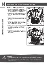
ASSEMBLY INSTRUCTIONS
ELECTRONIC SPEED ADJUSTMENT
The speed of your router is variable. At position “0”, there is no action; position “5” results in the
highest speed. Use the electronic speed adjuster (3) to produce uniform results in wood, plastics and
other materials. Use lower settings for large diameter bits and higher settings for small diameter bits.
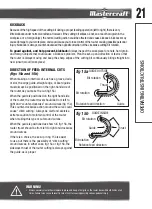
CHIP SHIELD
(fig 1)
The chip shield helps to keep dust and chips away
from the operator; they will not stop objects larger
than woodchips thrown from the bit.
The chip shield on the plunge base is held in position
by a screw. To remove the chip shield from the plunge
base, unplug the router and simply loosen the screw
and take the chip shield off of the base.
WARNING!
• To prevent personal injury, always disconnect the plug from the power source before assembly, adjustment or
changing of bits. Failure to comply with these instructions could result in accidental start-up and possible injury.
• To reduce the risk of injury, do not overload the tool. Let it work at its own pace. Guide the cord carefully to
avoid accidentally cutting it.
• Always wear eye protection. The chip shield deflector is not intended as a safety guard.
• Always turn the router motor off and unplug the router from the power source before making any adjustments
or installing accessories. Failure to turn the motor off and unplug the router could result in accidental starting,
which can cause serious personal injury.
CAUTION!
• Always have the chip shield deflector in place on the base when operating the router.
ASSEMBL
Y INSTRUCTIONS
Screw (included)
fig 1
FPO
Содержание 054-6988-6
Страница 2: ...headline bars continuation tabs notes warnings ...
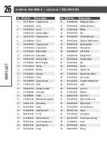
Страница 25: ...25 PARTS LIST EXPLODED VIEW ...
Страница 30: ......