


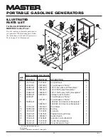

15
114716
OWNER’S MANUAL
WIRING DIAGRAMS
Figure 20 - Wiring Diagram, Model MGR2900
Resistance in Ohms
Stator
Stator
Rotor
Rotor
Capacitor,
Main
Auxiliary Primary Secondary
MFD
Diodes (2)
Model
Winding * Winding ‡ Winding † Winding † 450 Volt
1000 Volt
MGR2900
1.6
5.9
6.9
1.33
16
6 Amp
MGR4500I
0.835
1.852
4.91
—
40
8 Amp
MGR6000I
0.741
1.582
5.55
—
40
8 Amp
ELECTRICAL
COMPONENT
SPECIFICATIONS
* Connect T2 (green) and T3 (black). Measure resistance between T1 (red) and T4 (yellow).
‡ Resistance between brown and white leads.
† Remove diodes to check resistance.
T2
Stator
110/120V
T1
T3
T2
T4
L2
L1
Rotor
Stator
White
Brown
Auxiliary
Phase
Green
Red
Black
Yellow
Main
Windings
T1
T3
T4
L1
L2
L2
L1
20A
Circuit
Breaker
C
D
Receptacle
120V/15A
Y
el
lo
w
B
la
ck
Black
Yellow
GFCI
Black
HOT
WHITE
LIN
E


