background image

09

10

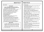
4.4


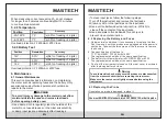
Continuity measurement

• 
  discharge.
• Set the rotary switch to the multi-function position.
  Press “

FUNC

” twice to enter continuity mode.

• Connect the red test lead to the input jack and the black 
  lead to the COM jack.
• Connect the leads to the circuit under test.If the 
  measured resistance is less than 30

Ω

, the buzzer will 

  sound.

Turn off power to the circuit. Allow all capacitors to 

WARNING

To prevent injury or damage to the meter,turn off
power to circuit and discharge all capacitors fully
before making continuity measurements. 

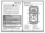
4.5


Diode test

• Turn off power to the circuit. Allow all capacitors to 
  discharge.
• Set the rotary switch to the multi-function position.  
  Press “

FUNC

” once to enter diode mode.

• Connect the red test lead to the input jack and the black 
  lead to the COM jack.
• Connect the red test lead to the anode (+) and the black 
  lead to the cathode (-) of the diode and read the 
  measurement on the display.  The meter will display 
  “OL” if the connection is reversed.

WARNING

To prevent injury or damage to the meter,turn off
power to circuit and discharge all capacitors fully
before making


diode measurements. 

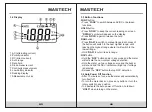
4.6


Battery test

• 
• Connect the red test lead to the input jack and the black 
  lead to the COM jack.
• Connect the red test lead to the positive (+) end and the
  black lead to the negative (-) end of the battery and read 
  the measurement on the display.

Set the rotary switch to the appropriate battery test range.

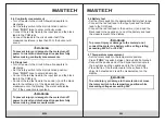
4.7 Temperature measurement

• 
  Press “

FUNC

” to switch between Celsius and Fahrenheit.

• Connect the positive end of the K-type thermocouple to 
  the input jack and the negative end to the COM jack.
• Place the tip of the thermocouple to the surface of the 
  object to be tested and read the measurement on the 
  display.

Set the rotary switch to the temperature position.  

To prevent injury or damage to the meter,do not
connect the meter to a battery with a voltage rating
exceeding 60V AC or 30V DC

WARNING

To avoid injury or damage to the meter,do not move
the rotary switch to the temperture position while
measuring


voltages


exceeding


30V

WARNING

Содержание MS8238C

Страница 1: ...al Digital Multimeter CAT III 600V MS8238C DIGITAL MULTIMETER Autorange Auto power off 9V 1 5V 12V FUNC HOLD RAN NCV 600V CAT III mA μA V TEMP mAμAV TEMP COM MAX 30 sec every 15 min MAX FUSED 10A MAX 200mA FUSED MAX 600V ...

Страница 2: ...7 4 1 AC DC voltage measurement 7 4 2 AC DC current measurementrent 7 3 4 Auto Power Off Function 6 5 Specifications 11 5 1 General Specifications 11 5 2 Technical Specifications 12 4 3 Resistance measurement 8 4 4 Continuity measurement 9 4 5 Diode test 9 4 6 Battery test 10 4 7 Temperature measurement 10 6 Maintenance 15 6 1 General Maintenance 15 6 3 Replacing the Probe 16 6 2 Replacing the Bat...

Страница 3: ... source first If not working properly the protective equipment may be damaged have the meter serviced before using Never measure voltages that may exceed the protection limit indicated on the meter Always be careful when working with voltages above 60V DC or 30V AC rms Keep fingers behind the probe barriers when making voltage measurements Make sure the test leads are in the correct input jacks be...

Страница 4: ...mediately A protective device may be damaged If there is any doubt please have the meter inspected by a qualified technician 2 3 Electrical Symbols AC DC Both direct and Alternating Current Important safety information High voltage with danger Ground Double Insulation Class II safety equipment Fuse must be replaced as per the specification herein Accord with the related EU laws and regulations AC ...

Страница 5: ... the non contact voltage detection Hold the meter up to a voltage source and the buzzer will sound and the NCV indicator will light up if voltage is detected Release the NCV button to stop NCV detection 3 4 Auto Power Off Function turn itself off To turn the meter back on press any button or turn the rotary switch to any position To deactivate the auto power off function hold down HOLD when turnin...

Страница 6: ... test lead to either the input or 10A jack and the black lead to the COM jack Break the circuit and connect the leads in series with the circuit black lead on the lower voltage side Turn circuit power on and read the measurement on the display If OL is display it means the measurement has exceeded the current range Move the rotary switch to a higher range 4 3 Resistance measurement discharge Set t...

Страница 7: ...ill display OL if the connection is reversed WARNING To prevent injury or damage to the meter turn off power to circuit and discharge all capacitors fully before making diode measurements 4 6 Battery test Connect the red test lead to the input jack and the black lead to the COM jack Connect the red test lead to the positive end and the black lead to the negative end of the battery and read the mea...

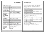
Страница 8: ...dication Display shows OL Low Battery Indication Temperature coefficient 0 1xaccuracy C 18 C or 28 C 5 2 Technical Specifications Accuracy of reading digits at 18 C 28 C with a relative humidity of 80 guaranteed for a period of one year Resolution Accuracy 2V 20V 0 01V 0 001V 5 2 2 AC Voltage Measuring range 0 5 of reading 5 digits 5 2 1 DC Voltage Input impedance 10MΩ Max input voltage 600V DC or...

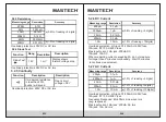
Страница 9: ...AC rms Display shows forward voltage drop Function Description Resolution 1 5V Diode Test Rang 1mV 20mA 200mA 10A 0 01mA 0 1mA 10mA Overload protection mA jack FF 400mA H 600V fuse 10A jack FF 10A H 600V fuse Max input current mA jack 200mA DC 10A jack 10A DC When measuring current exceeding 2A do not measure for longer than 2 minutes continuously Wait 10 minutes to continue measurement 5 2 7 AC C...

Страница 10: ... C 1 C 1 F 4 1382 F Position 2 0 of reading 2 digits Overload protection FF 400mA H 600V fuse 5 2 9 Battery Test Resolution Accuracy 12V 0 01V 0 01V 9V Position 0 8 of reading 7 digits 1 5V 0 001V 0 8 of reading 7 digits 3 0 of reading 5 digits Overload protection FF 400mA H 600V fuse 2 0 of reading 4 digits 6 2 Replacing the Battery and Fuses 6 3 Replacing the Probe 1 Under normal conditions it i...

Страница 11: ...R 00 05 1568 ...
Отзывы: