background image


23 

Run  the  burner  again  using  correct  fuel  and 
steps given in section 5.2 


Increased 
consumption of fuel 

1.  Burner  operated  with  the  damper  in 

“OPEN” position 
 

2.  After  extensive  use  of  the  combustor 

or  use  of  inappropriate  fuel,  the 
combustor  will  lose  its  efficiency  to 
generate extra heat.   

1.  It  is  important  to  “CLOSE”  the  damper  when 

the  burner  has  reached  a  sufficiently  hot 
temperature.    Refer  section  5.2  and  follow 
correct start-up, loading and re-fuelling steps 
 

2.  Carry  out  visual  inspection  and  cleaning  of 

combustor by following section 6.3, 6.4 & 6.5. 


Check  emission  coming  out  of  your  chimney 
by following steps in section 6.6 
 
Consult  your  dealer  about  the  other  possible 
causes 


Содержание WAIMAKARIRI ASH

Страница 1: ...ENCE Manufactured in New Zealand by GLEN DIMPLEX NEW ZEALAND LIMITED P O Box 58473 Botany Manukau 2163 Ph 0800 666 2824 Fax 09 274 8472 Email sales glendimplex co nz Web www glendimplex co nz 4th Mar 2020 Part No 599386 V1 1 Glen Dimplex New Zealand Ltd reserves the right to change specifications the content of this manual or the design of its product without prior notice ...

Страница 2: ...ONAL SEQUENCE 14 5 1 BEFORE FIRST LIGHT UP 14 5 2 COLD START UP 14 5 2 1 KINDLING INTERMEDIATE LOAD 1 14 5 2 2 INTERMEDIATE LOAD 2 14 5 2 3 MAIN LOAD 15 5 2 4 RE FUELING SHUT DOWN 15 6 0 CATALYTIC COMBUSTOR MAINTENANCE 16 6 1 HOW IT WORKS 16 6 2 BEST PRACTICES TO ENHANCE LIFE OF COMBUSTOR 16 6 3 INSPECTING CATALYTIC COMBUSTOR 17 6 4 REMOVAL OF CATALYTIC COMBUSTOR 17 6 5 CLEANING OF CATALYTIC COMBU...

Страница 3: ...rom the combustion gases The catalyst will then rise in temperature up to approximately 5000C and reaches its optimum stage During the initial light up phase with the damper in the open position the combustion gases are allowed to pass over and through the catalyst preheating the catalyst After approx 20 minutes the catalyst will reach the required temperature At this stage the damper is closed an...

Страница 4: ...by Glen Dimplex New Zealand The catalytic combustor used in the Waimakariri ULEB must be inspected and maintained periodically Read section 6 0 on the monitoring and maintenance of the catalyst carefully and follow the instructions 1 4 Caution This appliance is not intended for use by persons including children with reduced physical sensory or mental capabilities or lack of experience and knowledg...

Страница 5: ...port Flue System For installation in Canterbury South of Canterbury we recommend extending 200 outer casing within 250 300 from termination of flue Floor Protector Requirement Ash Floor Protector Clearances to Combustibles Parallel Installation Corner Installation A Rear Panel to Rear Wall 100 mm C Glass to Floor Protector Front 300 mm B Cooktop Edge to Side Wall 180 mm E Cooktop Corner to Wall 10...

Страница 6: ...ess than 600mm above the ridge If the flue exits further than 3 meters out from the roof ridge then it must project at least 1000mm above roof penetration This dimension may need increasing to ensure that the top of the flue is at least 3 meters away from the roof or other obstruction when measured horizontally The flue pipe shall extend not less than 4 2m above the top of the burner Due to factor...

Страница 7: ...specified in section 2 0 of this manual can be safely reduced by following guidelines specified in AS NZS 2918 2001 table 3 1 3 2 Heatshield should be made of non combustible material like metal or masonry Installed between the burner and the combustible wall With an air gap behind it and vented top and bottom The shield should extend a minimum of 450mm beyond the top of the appliance and extend w...

Страница 8: ... The figure below gives the holes that can be pre drilled on the floor protector with respect to the flue center We recommend a minimum size of 8mm DynaBolts on the concrete floor or 8mm coach screws or toggle fasteners for wooden floors of appropriate length Two holes are located at the rear of the burner ...

Страница 9: ...left and the right side wall of the firebox on its side edge Push these bricks towards the rear of the firebox Lastly install one x 123 long cut brick each on the left and right side wall towards the front of the firebox Step 2 The baffle is already in place Check that the baffle is locked in place by trying to move it front to back there is a location tab at the rear which locks it in place and t...

Страница 10: ... the top of the baffle Away from the left and right walls of the firebox there are two more pins 6 7 on the top of the front baffle flange to act as a stopper for the arrester plate Step 6 Unpack the catalytic combustor Hold the combustor vertically with both hands in front of the door opening Hold the combustor more towards the right so that it does not hit the left front stopper plate 1 2 Lift a...

Страница 11: ...op Once locked into the left side push the right end of the combustor towards the rear so that on the right it is between rear strip 3 and the right front stopper pin 4 The combustor should be fully pushed left and be leaning forward at the top Cross check it is positioned correctly Step 8 With the damper still in OPEN position Take the stainless steel flame arrestor plate and hold vertically ensu...

Страница 12: ...tab end of the tube into the hole on the right wall of the firebox Tilt and lift the tube till the tab on the tube can be engaged with the pin on the left wall of the firebox Weave the R clip into the small hole on the pin on the right Ensure that the tube is secured by pushing the tube both towards left and right Step 10 Refer schematic below to check the configuration of all internal firebox com...

Страница 13: ...ot burn coal driftwood treated or painted wood highly resinous wood such as Old Man s Pine plastic plywood chipboard garbage flammable fluids such as gasoline naphtha engine oil refuse milk cartons colored or printed paper The combustion of such materials can emit toxic corrosive and hazardous fumes that will pollute the environment 4 1 Testing Your Wood Moisture There are several ways to confirm ...

Страница 14: ... base of the firebox 3 Stack around 15 16 very small kindling pieces on top of these logs This initial light up procedure is the Top Down Start Up method which reduces the particle emission during the start up phase considerably 4 Place the firelighters on top of kindling and light the fire We recommend green firelighters made of wood waste 1 2 3 4 5 2 2 Intermediate load 2 5 Keep the door ajar sl...

Страница 15: ...air slide to HIGH setting and wait for at least 30 secs 2 Unlatch the door and keep it slightly ajar for 15 20 seconds 3 Then open the door fully Always switch the damper handle gently and gradually This practice is important to avoid puff of smoke coming into room or damage to the catalytic combustor 5 2 4 Refueling and Shut down 14 Before opening the door for reloading make sure that the damper ...

Страница 16: ...p the damper open until the catalytic combustor becomes sufficiently hot approximately 20 25 mins During the start up phase the lower firebox temperature creates a larger volume of unburnt particles These particles will tend to adhere to the combustor s surfaces due to insufficient temperature If the damper is closed during start up these may block the combustor and make it less efficient Avoid le...

Страница 17: ...mbustor If the clogging is due to tarry or granular brown substance use the Hot Burn technique described in section 6 5 to burn off the clogging 6 4 Removal of Catalytic Combustor The first step is to remove the flame arrestor plate Use special tool supplied with your burner to remove the flame arrestor plate Insert the tool into the holes which are at the center of the flame arrestor plate and pu...

Страница 18: ...Less output Increased fuel consumption Visual deterioration of the combustor plates Visual increase in emissions Before concluding that the combustor needs replacement ensure that you are using your burners with all the tips given in section 6 2 Mainly the correct fuel and the damper operation Further inspect the combuster carefully by following steps in section 6 3 6 4 and if needed clean the com...

Страница 19: ...kariri combustor pictures in different states New combustor Combustor fitted inside the firebox Flame arrestor plate installed Glowing combustor inside the firebox The tool provided for removal of arrestor plate Damaged combustor Clogged combustor ...

Страница 20: ...tly can continue to be used The bricks should be replaced only when they are damaged enough in place and cannot perform their intended task Refer section 3 7 for location and sequence of assembly of bricks in the firebox of the Waimakariri ULEB After removing the old bricks remove all the ash from the firebox by removing the ash plug and collect it in the ash drawer using a brush For pedestal or l...

Страница 21: ...ated parts Catalytic Combustor St St Flame Arrestor Plate Damper plate lifting mechanism Baffle Front air deflector Front Air Tube Rear Air Tube Glass Main Door Glass Other Spare Parts Kits available Damper Handle Kit Main Door Handle Kit These consumable parts should be replaced as soon as they show signs of wear Running your burner with worn or broken parts may result in reduced output an increa...

Страница 22: ...ion fans which cause extreme negative pressure in the house when they are operating This negative pressure works against the flue system draft In severe cases the negative pressure in the house overcomes the flue system draft and the appliance begins to spill smoke especially when a fire is started or when it dries down to coals Also it can starve fire from air needed resulting in poor performance...

Страница 23: ... will lose its efficiency to generate extra heat 1 It is important to CLOSE the damper when the burner has reached a sufficiently hot temperature Refer section 5 2 and follow correct start up loading and re fuelling steps 2 Carry out visual inspection and cleaning of combustor by following section 6 3 6 4 6 5 Check emission coming out of your chimney by following steps in section 6 6 Consult your ...

Страница 24: ...24 ...

Страница 25: ...d welcome your feedback on the following questionnaire Question Please tick appropriate remark 1 General presentation of Product Excellent Good Ok Needs to Improve 2 Styling and Looks Excellent Good Ok Needs to Improve 3 Packaging Excellent Good Ok Needs to Improve 4 Is documentation easy to follow and informative Excellent Good Ok Needs to Improve 5 Fixtures Fittings Loose parts In order Items mi...

Страница 26: ...26 ...

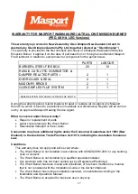
Страница 27: ... Reasonable transport or travel costs Consumers may have additional rights under the Consumer Guarantees Act 1993 New Zealand or the Australian Trade Practices Act 1974 including the Australian Consumer Law Conditions This warranty does not apply and will be void where The Wood Burner is not installed in accordance with AS NZS2918 2001 or any building code or consent The Wood Burner is not install...

Страница 28: ...sequential losses or special damages of any kind including costs of collection and delivery other than repair or replacement of products or components under this warranty where any goods are acquired or used for the purposes of a business How to obtain warranty service Completed Warranty registration form previous page needs to be mailed within 30 days of installation to your Glen Dimplex Warranty...

Отзывы: