Operating Manual TANGO 3 mini
Stepper Motor Controller for Micropositioning Systems
Страница 1: ...Operating Manual TANGO 3 mini Stepper Motor Controller for Micropositioning Systems ...
Страница 2: ... Order no 00 76 100 5800 Manufacturer Märzhäuser Sensotech GmbH An den Fichten 35 35579 Wetzlar Germany Tel 49 6441 67106 24 Fax 49 6441 67106 28 info marzhauser st com www marzhauser st com 2018 All rights reserved Reproduction even in part is only permitted following written permission from Märzhäuser Sensotech GmbH ...
Страница 3: ...stalling SwitchBoard 13 5 4 Familiarising Yourself with SwitchBoard 13 5 5 Connecting the Controller to SwitchBoard 13 6 Port Assignment 15 6 1 Motor 1 3 D Sub 26 Pin Socket 15 6 2 HDI 5 Pin Mini USB 16 6 3 USB 4 Pin USB Socket Type B 16 6 4 Encoder 1 3 HD D Sub 26 Pin Plug 16 6 5 AUX mini HD D Sub 15 Pin Plug 18 6 6 DC IN 2 1 mm DC Plug 18 7 Technical Data 19 8 Accessories 22 8 1 External Power S...
Страница 4: ...Basics of the Operating Manual Operating Manual 4 ...
Страница 5: ... manual 2 Safety 2 1 Intended Use The controller has been designed and constructed exclusively for the connection of 2 and 4 phase stepper motors and such input devices which have been approved by Märzhäuser Sensotech for operation with this controller Märzhäuser Sensotech accepts no liability for faults which can be traced back to unusual or exceptional use or improper treatment 2 2 Installation ...
Страница 6: ...ntroller might be changed For this reason only use the 24 V wide range power supply provided In case of violation all warranty and liability claims will become void If unsuitable peripheral devices are connected the operator can suffer an electric shock and damage can be caused to the controller The controller itself does not have a protective ground terminal Ensure that no dangerous voltages or c...
Страница 7: ...value can correspond to the DC voltage at the plug 24V DC 4A max In the event of malfunction faults or safety risks related to the controller or the power supply switch off all the devices concerned and disconnect them from the mains supply by removing all plugs for example Secure the devices concerned to prevent them being switched back on again and contact our Customer Service Center The control...
Страница 8: ... for 35 mm top hat rail 00 76 100 0800 4 Product Description 4 1 Identification You can find all required information for clear identification of the controller on the identification plate 4 2 Area of Application The controller can be operated in 2 different modes Manual mode Control of the connected axes exclusively via operating element Joystick digital or ERGODRIVE digital Automatic mode Contro...
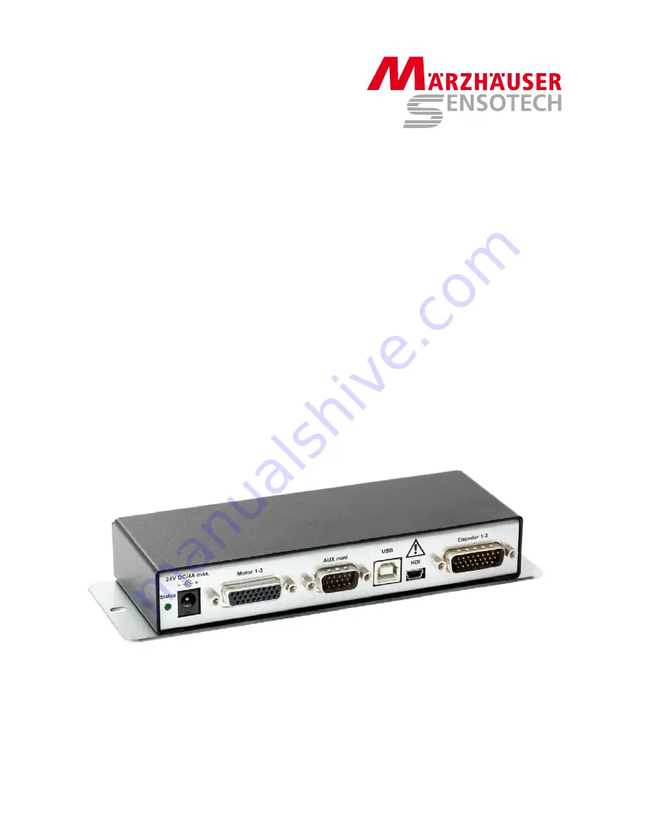
Страница 9: ...1 Rear panel port Encoder 1 3 optional All the controller s ports are located on the rear panel The assignment of the ports and the respective technical data can be found in chapter 6 Port Assignment page 15 4 4 2 Status LED Status Description Off Controller is not ready On Controller is ready Flashes approx 1x sec Bootloader active1 Flashes approx 3x sec Output stages switched off2 Flashes approx...
Страница 10: ...positioning system scanning stage and or focus drive to the port Motor 1 3 Use a suitable motor cable from Märzhäuser Sensotech for this 4 Encoder interface option Connect the encoder ports of your positioning systems to the port Encoder 1 3 Use a suitable encoder cable from Märzhäuser Sensotech for this 5 Operating element option Connect the operating element Joystick digital or ERGODRIVE digital...
Страница 11: ...er and the PC takes place over a USB connection via a virtual COM port To be able to connect the controller to your PC via USB cable you require Windows 2000 Windows XP 32 64 bit Windows Vista 32 64 bit Windows 7 32 64 bit Windows 8 32 64 bit or Windows 10 32 64 bit Observe the following notes regardless of the version of your operating system Do not connect to Windows Update Continue installing t...
Страница 12: ...not programming the controller via the software provided by Märzhäuser Sensotech SwitchBoard DLL files make sure that your RS 232 interface is configured correctly 57 600 Baud 11 bit frame 1 start bit 8 data bits 2 stop bits Check the connection of the PC with the controller using the ver instruction for example The controller sends the version number back as the feedback value Note Further instru...
Страница 13: ...rting SwitchBoard by pressing the F1 key Alternatively you will also find the SwitchBoard Operating Manual in the download section of the Märzhäuser website under www marzhauser com downloads 5 5 Connecting the Controller to SwitchBoard Identifying the COM port Before you can connect the controller to SwitchBoard you must identify the COM port used by the controller 1 Open the Device manager Windo...
Страница 14: ...o your positioning or overall system can be the result Ensure that the radio button Read setup from controller is always enabled Only enable the radio button Send setup to controller when our Customer Service Center requests you to do so 5 Click the button Connect When the colour of the display field on the right of the button Connect and the colour of the display field in the bottom left hand cor...
Страница 15: ... 11 MOT3PH1 Motor 3 phase 1 12 MOT3PH2 Motor 3 phase 2 13 MOT3PH2 Motor 3 phase 2 14 END30 Limit switch axis 3 zero point1 15 END3END Limit switch axis 3 end position1 16 BRAKE Connection for a brake3 17 5VEXT1 5 V2 18 GND GND 19 MOT2PH1 Motor 2 phase 1 20 MOT2PH1 Motor 2 phase 1 21 MOT2PH2 Motor 2 phase 2 22 MOT2PH2 Motor 2 phase 2 23 END20 Limit switch axis 2 zero point1 24 END2END Limit switch ...
Страница 16: ...ve signal 150 Ω Pin 16 filter1 8 U2X3 Axis 3 phase 2 cosine negative signal 150 Ω Pin 17 filter1 9 GND 10 U1X1 Axis 1 phase 1 sine positive signal 150 Ω Pin 1 filter1 11 U2X1 Axis 1 phase 2 cosine positive signal 150 Ω Pin 2 filter1 12 5V_ENC 5V_ENC Imax 0 75 A 13 U1X2 Axis 2 phase 1 sine positive signal 150 Ω Pin 4 filter1 14 U2X2 Axis 2 phase 2 cosine positive signal 150 Ω Pin 5 filter1 15 5V_EN...
Страница 17: ...requency position signal approx 250 kHz approx 250 kHz 30 ns flank clearance MR and 1Vpp signals are counted at even higher frequencies such as RS 422 5 Max frequency of the position signal during reference run 6 kHz 6 kHz 40 ns flank clearance Reference signal is synchronised with the position signal 6 Max achievable interpolation factor 98 800 fold 205 800 fold 4 fold Related to a signal period ...
Страница 18: ...ter low pass 470 Ω 100 nF then Ri 6 8 kΩ 6 TAKT_OUT HCMOS output 5 V Clock output for T V R operation of an external axis2 7 V R_OUT HCMOS output 5 V Forward backward output for T V R operation of an external axis2 8 SHUTTER_OUT HCMOS output 5 V Actuation of an external shutter control2 9 TRIGGER_OUT HCMOS output 5 V Synchronous trigger2 10 CANH CANH CAN Bus port CANH 11 ANOUT0 Analog out Resoluti...
Страница 19: ...g max 2 6 m with 200 step motor and 1 mm ball screw pitch Instruction set TANGO native Venus 1 Venus 2 others on request Safety functions Voltage monitoring 3 3 V Reset Monitors 3 3 V triggers reset in the event of undervoltage Voltage monitoring VCC5 Monitors 5 0 V triggers PSE in the event of undervoltage Undervoltage monitoring DC IN Controller on Ue 18 6 20 1 V Controller off Ue 16 9 19 0 V Ov...
Страница 20: ...ni For connection of the controller to other peripheral devices max 1 MBaud Note The CAN interface is a customer specific interface Please contact our Customer Service Center if you have any questions Special functions at the port Motor 1 3 TRIN1 TTL input can be read via software e g to release the motor brake 1 BRAKE Port for motor brake 24 V max 0 5 A can be controlled via software ETS Interfac...
Страница 21: ...t of current consumption Current consumption can be read by software1 1 The current consumption depends on motor type motor current voltage supply number of motors number of revolutions current consumption of peripherals etc The following applies as a guidance value Imax 24 V approx 1 3 sum of all motor currents 0 2 A for logic voltages 0 1 A per encoder without further peripherals Separate measur...
Страница 22: ...s Operating Manual 22 8 Accessories 8 1 External Power Supply Model Adapter Technology ATS072T P240 24 V 3 A C14 mains plug Note Protective ground and GND are connected Fig 2 Data sheet for external power supply ...
Страница 23: ...AUX mini connects Pin 5 PSE to Pin 3 5V at the port AUX mini If the start up adapter AUX mini has been inserted the output stages can be enabled If the start up adapter AUX mini is not inserted or if Pin 5 is open at port AUX mini or set to GND the output stages are disabled Fig 3 Start up adapter AUX mini ...
Страница 24: ...unction Wheel Art no 00 76 300 1821 Fig 7 4 Axes Joystick digital with Multi Function Wheel Art no 00 76 400 1820 Operating elements and LED Fig 8 Operating elements and LEDs Fig shows 4 Axes Joystick digital with Multi Function Wheel No Operating element LED 1 F1 key 2 F2 key 3 F3 key 4 F4 key 5 Control stick with rotary potentiometer rotary potentiometer only on 3 Axes Joystick digital and 4 Axe...
Страница 25: ... multi function wheel Exchange of assignment of control stick deflection and axis to be moved X Y Blocking of axes Programming of the path to be travelled per revolution of the multi function wheel Assignment of the multi function wheel to any axis Control of the LED illumination LED 100 by control stick or multi function wheel Depending on the configuration the function keys F1 F4 permit fast acc...
Страница 26: ...gital Art no 00 27 322 7000 Fig 10 ERGODRIVE 3 digital Art no 00 27 322 8000 Operating elements and LED Fig 11 Control elements Fig shows ERGODRIVE 3 digital Rotation of the drive knobs and the Z wheel is synchronous to travel e g 1 revolution on the drive knob Z wheel 0 1 mm change in position in the corresponding axis No Operating element LED 1 X drive knob 2 Y drive knob 3 Z wheel only on ERGOD...
Страница 27: ...manual programming of the controller The states of drive knobs Z wheel and function keys can be queried via the software interface or be evaluated by the controller Configuration options for the ERGODRIVE excerpt Individual configuration of travel speeds Move X Y axis synchronously using X drive knob Configure Z wheel assignment any axis LED 100 Enable disable toggle mode for XY Z key Configure F1...
Страница 28: ...rating Manual 28 8 5 Mounting Plate Fig 12 Mounting plate for screw attachment Fig 13 Dimensions of the mounting plate Dimensions controller incl mounting plate 189 6 31 5 62 mm W H D Dimensions slotted holes 4 5 7 mm ...
Страница 29: ...sktop Accessories Märzhäuser Sensotech GmbH 29 8 6 Mounting Adapter for 35 mm Top Hat Rail optional Fig 14 Mounting adapter for 35 mm top hat rail Dimensions controller incl mounting adapter 164 48 62 mm W H D ...
Страница 30: ...troller or the wall socket with wet hands Danger to life and possible device damage through the spread of substances which are harmful to health The controller and accessories are not protected against corrosive infectious toxic radioactive or other substances which are harmful to health Improper use of the controller can lead to health damage or even death as well as to device damage on the contr...
Страница 31: ...replacements User training also online via web conference You can reach our Customer Service Center Mondays to Fridays from 08 00 am to 16 00 pm CET Tel 49 6441 9116 36 Fax 49 6441 9116 40 E mail service marzhauser com 12 Taking out of Service Equipment damage possible through putting into taking out of service with existing mains power connection While the controller is connected to the voltage s...
Страница 32: ... of via a communal collection point for electrical and electronic equipment Return the controller to Märzhäuser Sensotech for free and proper disposal 1 Take the controller out of service 2 Pack the controller and accessories properly 3 Send the controller to Märzhäuser Sensotech GmbH An den Fichten 35 35579 Wetzlar Germany Note All equipment purchased from Märzhäuser Sensotech can be returned at ...
Страница 33: ...TANGO Desktop Declaration of Conformity Märzhäuser Sensotech GmbH 33 14 Declaration of Conformity Fig 15 Declaration of Conformity ...
Страница 34: ...Declaration of Conformity Operating Manual 34 ...