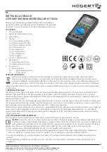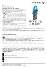
1. Volt - Input Terminal
This is the positive input terminal for VOLT measurements. Connection is made
to it using the red test lead.
2. COM - Common Terminal
This is the negative (Ground) input terminal for all measurement modes except
current. Connection is made to it using the black test lead.
3. Hz
Ω
Frequency, Ohms, Diode Input Terminal
This is the positive input terminal for frequency, Ohms and diode
measurements. Connection is made to it using the red test lead.
4. Display
The display indicates the measured value of signal, function mode, low battery,
range, peak and hold settings.
5. Function / Range selector rotary switch
The rotary switch selects the function and desired range
6. PEAK - Peak recording mode
This function is used to measure the peak value of an AC current signal.
7. RANGE Button
Selects the manual ranging mode.
8. Hold Button
Freezes the last reading displayed.
9. Clamp Jaws
Detects AC current flowing through the conductor on test.
10. Trigger
Press the lever to open the clamp jaws.
3
1.2 Unpacking and Inspection
Before unpacking the clampmeter, examine the shipping carton for any sign of
damage. Unpack and inspect the clampeter and any associated leads for dam-
age. If there is any damage then consult your distributor immediately.
Upon removing your new Digital Clamp Meter (DCM) from its packaging, you
should have the following items:
1. Digital clampmeter
2. Test lead set (one black, one red)
3. 9-Volt battery (installed in meter)
4. Instruction manual
5. Protective carry case
If any of the above items are missing, please contact your distributor immediately.
1.3 REPLACING THE BATTERY
This meter is powered by a NEDA type 1604 or equivalent 9-volt battery. When
the meter shows the "
" the battery must be replaced to maintain correct
operation. Follow the procedure below to replace the battery.
1. Disconnect the test leads from any live source, turn the rotary switch to off
and remove the test leads from the input terminals
2. The battery cover is secured to the bottom case by a screw. Using a Phillips
head screwdriver, remove the screw from the battery cover. The cover will now
come away from the instrument.
3. Replace the battery with a new equivalent 9-volt one observing correct polarity.
4. Replace the battery cover and re-install the screw.
WARNING
To avoid electrical shock, disconnect the test leads
and any input signals before replacing the battery.
Replace only with same type of battery.
4
2 SAFETY INFORMATION
The instrument complies with class II overvoltage CAT III 1000V of the
IEC1010-1 (EN61010-1) ; UL3111-1; and CAN/CSA C22.2 #1010.1-92
standards, pollution degree 2 in accordance with IEC-664 indoor use. If the
equipment is used in a manner not specified, the protection provided by the
equipment may be impaired.
This product complies with the requirements of the following European
Community Directives: 89/336/EEC (Electromagnetic Compatibility) and
73/23/EEC (Low Voltage) as amended by 93/68/EEC (CE Marking).
Electrical noise or intense electromagnetic fields in the vicinity of the equipment
may disturb the measurement circuit. Measuring instruments will also respond to
unwanted signals that may be present within the measurement circuit. Users
should exercise care and take appropriate precautions to avoid misleading
results when taking measurements in the presence of electromagnetic
interference.
5
3. OPERATION
3.1 VOLTAGE MEASUREMENTS
1. Turn off power to the circuit/device under test and discharge all capacitors.
2. Plug the black test lead into the COM input jack on the meter and connect the
test lead tip to a grounded point (the reference point for measured voltage).
3. Select the desired AC voltage range (V
), or DC voltage range (V
). If the
magnitude of the voltage to be measured is unknown, always start with the
highest range.
4. Plug the red test lead into the volt input jack on the meter and connect to the
circuit where a voltage measurement is required. Voltage is always measured in
parallel across a test point.
5. Energise the circuit or device under test and make the voltage measurements.
Reduce the range setting if set too high until a satisfactory best resolution read-
ing is obtained.
6. After completing the measurement, turn off the power to the circuit / device
under test, discharge all capacitors and disconnect the meter test leads.
3.2 CURRENT MEASUREMENTS
1. Set the rotary function switch to ACA 1000A Range.
2. Press the trigger to open the clamp jaws and clamp them around a conductor.
Jaws should be completely closed before taking a reading.
3. The most accurate reading will be obtained by keeping the conductor across
the centre of the clamp jaws.
4. The reading will be indicated on the display
5. Reduce the range if set too high until a satisfactory best resolution reading is
obtained.
6
WARNING
To avoid possible electric shock, instrument damage and / or
equipment damage, do not attempt to take any voltage measurements
if the voltage is above 1000V DC or 750VAC. These are the maximum
voltages that this instrument is designed to measure. The "COM"
terminal potential should not exceed 500V measured to ground.


