GB
- 5 -
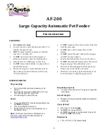
Plan C
Restriction to the entry to the garden
Plan D
Whole garden boundary with exclusion
areas
Key
Twisted wire, which cancels the signal
Working signal
Once the boundaries are set, the different
components can be installed.
Step 2: Install the transmitter
The transmitter must be installed indoors
(e.g. in a garage) near a power socket in a
safe, dry place where the temperature is
always above 0°C, away from direct sun-
light, and not exposed to the weather or
splashes,
IMPORTANT
.
To avoid electrical interference, do not
install the transmitter near large metal
objects such as electrical cabinets, hot
water tanks, metal garage door tracks or
operating household appliances such as
washers and dryers. Do not mount the
transmitter next to a circuit breaker panel.
Do not run the wire alongside electrical or
telephone wires, TV cables or antenna
wires or near a satellite dish.
Mount the transmitter on a wall at least
1 m from the ground using countersunk
screws of maximum diameter 4 mm.
The connections to the mains and the
boundary wire are described in Step 4.
Step 3: Lay the boundary wire
Lay the wire around the edge of the
containment areas as shown on your
ground plan.
Basic guidelines
The wire must run from and back to the
transmitter in a continuous loop.
Starting at the transmitter end, lay the
wire along the planned route. You can
just lay it on the ground if you want a
temporary system, or bury it, or attach it
to a pre-existing fence (at a height no
more than 0.50 m from the ground).
To prevent the signal operating in part
of the garden, twist the ‘out’ and ‘in’
wires together with at least 15 twists
per metre. This cancels out the signal
and so the dog is not affected. The two
wires must always be running in oppo-
site directions for the signal to be can-
celled out.
Always make rounded corners (1.5 m
radius). Square corners reduce signal
range.
In the case of a double loop such as in
Plan C, keep a distance of at least 1.5
m between the ‘out’ and ‘in’ wires to
prevent loss of signal range.
Step 4: Connect the antenna wire
to the transmitter
Connect the antenna wire to the transmit-
ter by stripping 1 cm of insulation from the
ends and connecting them to the trans-
mitter terminals.
Plug the transmitter into the mains: the
green light will come on.
IMPORTANT.
- When the transmitter is operating cor-
rectly the green light will stay on all the
time.
- If it blinks and the transmitter beeps, this
means the loop formed by the antenna
wire is broken (loose connection to the
transmitter terminals or severed wire).
- If the green light is out the transmitter is
not working – power cut or faulty trans-
former or circuit board.
See 7. Repair of the system in the event of
malfunction
Step 5: Check that the set-up is in
working order using the collar
receiver
a) Activate the collar receiver (do not fill it)
- Use the disc provided to unscrew the lid
of the battery compartment.
- Slide the battery into the compartment -
end first. The + end must be visible
when the battery is in place, as shown
on the battery polarity label on the back
of the collar.
- Use the disc to screw the lid of the bat-
tery back in, pressing down lightly on
the battery. Proper closure of the battery
compartment is necessary to keep the
receiver collar watertight.
- The receiver will emit a beep.
b) Set the control to minimum and check
that the system is working
- Bring the collar receiver close to the
antenna wire, about 30 cm from the
ground, to make sure it is working cor-
rectly. You should hear a beep when you
move close to the wire.
- Check along the whole of the boundary.
Important: the dog should be brought into
the containment area only if the prelimi-
nary beep test gives a positive result.
Step 6: Set the range control
- You can set the distance at which the
collar picks up the signal from a mini-
mum distance to a maximum of 6 m.
Diagram of control
When you turn the knob counterclockwise
you reduce the distance at which the
signal can be picked up by the receiver.
When you turn the knob clockwise you
increase the distance at which the signal
can be picked up by the receiver.
IMPORTANT.
You should first observe how your dog
behaves when trying to leave the contain-
ment area. A dog needs to gather speed to
cross an obstacle by jumping or climbing
over it. It is important to act when the dog
is starting to gather speed. You should
therefore locate the area where the dog
starts to gather speed and set the range
control accordingly. Conversely, for a dog
that seeks to leave the area by digging or
squeezing under a fence the spray needs
to be actuated close to the obstacle.
Step 7: Place the boundary flags
Place the flags where the beep can be
heard at intervals of 3 to 6 m. The flags
are a temporary visual boundary for your
dog to see the area it must not leave. Once
your dog is familiar with the “authorised”
area they can be removed.
IMPORTANT.
When the collar receiver beeps, leave the
forbidden area promptly.
Step 8: Conceal the antenna wire
Once the system has been checked you
can conceal the wire:
a) underground
- Dig a trench about 7 cm deep where you
want to run the wire. Burying the wire
protects it from damage and stops peo-
ple tripping over it and hurting themsel-
ves.
- Make sure you leave some slack, becau-
se the wire will contract and expand with
variations in temperature.
- Press the wire into the ground, taking
care not to damage it.
- Fill the trench
b) in a hard material (e.g. concrete slab)
- Run the wire along an expansion joint or
use a masonry disc cutter to make a
groove in the concrete about 3 cm deep.
- Place the wire in the groove and fill it
with silicone sealant. Your local DIY dea-
ler will help you choose the most suita-
ble sealant according to the type of sur-
face.
c) in water
- Run the wire through a flexible conduit
or PVC hose.
Transmitter
‘Out’ wire from the transmitter
‘In’ wire to the transmitter
Содержание Dynavet Zone Protector
Страница 1: ...062247 02 www martinsellier com Images non contractuelles Non contractual pictures ...
Страница 2: ......