8
9
410HJS
Joe Satriani Edition
100W Valve Amplifier
2
0
10
1
0
10
0
10
0
10
0
10
0
10
0
10
0
10
0
10
0
10
0
10
0
10
0
10
0
10
0
10
0
10
0
10
0
10
0
10
0
10
0
10
0
10
0
10
0
10
0
10
0
10
0
10
0
10
OD1
CLEAN
VOLUME
BASS
MIDDLE
TREBLE
GAIN
VOLUME
Orange & Red
BASS
MIDDLE
TREBLE
GAIN
GAIN
TREBLE
MIDDLE
BASS
VOLUME
GAIN
TREBLE
MIDDLE
BASS
VOLUME
CRUNCH
OD2
PRESENCE
RESONANCE
OFF
0
I
POWER
ON
STANDBY
FOOTSWITCH/
MIDI PROGRAM
FX LOOP
MASTER 2
ENABLE
OD1
MODE
OD2
MODE
CLEAN
MODE
CRUNCH
MODE
INPUT
MASTER
GATE THRESHOLD
OD1
CLEAN
CRUNCH
OD2
MID-SHIFT
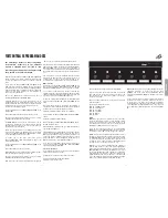
9. OD2 CHANNEL
See page 6 and 7 for full explanation.
10. MID-SHIFT SWITCH
This activates the Mid-Shift which only works on the OD1
and OD2 channel modes. This switch shifts the mids lower
and produces a slight “scoop.” The mid shift is indicated
by a blinking light in the footcontroller display.
11. CLEAN CHANNEL
See page 6 and 7 for full explanation.
12. CRUNCH CHANNEL
See page 6 and 7 for full explanation.
13. MODE SWITCHES
Pressing a MODE button has two functions:
When a mode button is used to change the amplifi er
channel, the last used mode of the selected channel is
selected.
When pressing the same mode button it cycles the modes:
GREEN > ORANGE > RED > GREEN...
Each mode remembers the FX, Gate and Master settings
- plus, in the case of the OD1 and OD2 channel modes, it
also remembers if the Mid-Shift is activated or not.
Example: You are in OD1 ORANGE with FX + GATE and
you press CLEAN. The amp switches to the last Clean
mode you had (let’s assume it was CLEAN GREEN with
MASTER 2). If you press the OD1 switch you go back
to OD1 ORANGE with FX + GATE. This allows bouncing
between channels without losing the settings. If you now
press OD1 again, you go to OD1 RED with whatever FX,
MASTER, GATE and MID-SHIFT settings you had last time
you were in this mode.
1. MAINS (POWER) SWITCH)
This is the On/Off switch for the mains electric power to
the amplifi er.
2. STANDBY SWITCH & SILENT RECORDING
The STANDBY Switch is used in conjunction with the
POWER Switch to ‘warm up’ the amplifi er before use and
to prolong the life of the output valves.
When the amplifi er is in standby mode the whole preamplifi er
section continues running at its nominal voltages whilst the
power amplifi er remains in a standby status. This allows the
amplifi er to be used for silent recording or preamplifi cation
purposes.
Only when the STANDBY is off can the amplifi er be used
without a lo ad. Always ensure a load is connected when
leaving the silent recording mode, i.e. when switching the
STANDBY switch ON.
3. FX LOOP
Pressing FX LOOP switches the FX loop ON and OFF in
the current channel. This is a programmable FX loop which
features a Return Level control on the rear panel and it is
located after the pre-amp and the Noise Gate. Pressing
the FX Loop switch engages this FX loop. Please refer to
the Serial Loop description later on in the handbook for its
operation.
MASTER SECTION
4. PRESENCE, RESONANCE
These controls are power amplifi er controls and only
have effect when playing through a speaker (not in silent
recording). They affect how the power amplifi er reacts
to the connected speakers and how much control the
amplifi er has over them.
Increasing the RESONANCE control emphasises the natural
speaker resonance for an improved bass response. In the
same way, increasing the PRESENCE control emphasises
the speaker’s high frequencies which will be heard as an
improved high frequency response which adds presence
to the sound.
Presence and Resonance constitute a powerful power
amplifi er equaliser, allowing responses from a ‘^’ shape
when they are fully off, which is felt as a mid boost, to a ‘v’
shape when they are turned clockwise, which is felt as a
scooped sound. Again, the effectiveness of these controls
is highly dependant on the kind of connected speakers.
Care has to be taken to avoid over excursion of the speaker
cones in high resonance settings.
5. FOOTCONTROLLER / MIDI PROGRAM
This switch has a dual function:
Pressing it once we enter the FOOTCONTROLLER
PROGRAM mode. It is indicated by a continuous red light.
Pressing it twice we enter the MIDI PROGRAM mode. It is
indicated by a blinking red light.
6. MASTER 1 / MASTER 2
These are the master volume controls of the amplifi er. They
can be assigned individually to each of the modes as you
wish and their setting will be remembered in each of the
modes. They are switched using the MASTER 2 button to
switch between MASTER 1 and MASTER 2.
7. GATE THRESHOLD CONTROL
Pressing ENABLE switches the noise-gate ON and OFF
in the current channel. Alongside the GATE switch each
channel has its own Gate control allowing individual level
settings of the effect.
8. OD1 CHANNEL
See page 6 and 7 for full explanation.
FRONT PANEL OPERATION
10
9
12
11
8
14
7
6
4
3
5
1
2
14. INPUT JACK SOCKET
You must always use a screened (shielded) guitar cable
and never use an unscreened (unshielded) speaker cable.
Also, this cable should be one of good quality. If you are in
any doubt regarding this, your Marshall dealer will be more
than happy to help and advise you.
13
13
ENGLISH
Содержание JVM410HJS Joe Satriani
Страница 1: ......


