OWNER’S MANUAL
MODEL HT18 AUTOTOAST™ HORIZONTAL TOASTER
144328 RV121814
1
Copyright
2013 Marshall Air Systems, Inc.
All Rights Reserved.
INSTALLATION
PRE-INSTALLATION
1. The toaster is packaged to minimize the risk of shipping damage. Immediately upon receipt, make certain
to inspect the unit for damage.
FILE ALL CLAIMS WITH THE FREIGHT CARRIER.
2.
It is necessary to check your voltage at the receptacle.
The voltage should match the toaster name
plate.
CAUTION: DO NOT REMOVE THE ELECTRICAL CONTROL PANEL COVER ON THE RIGHT
SIDE OF UNIT WITHOUT FIRST TURNING OFF THE TOASTER AND UNPLUGGING THE TOASTER.
See Figure 8 for instructions.
FINAL INSTALLATION
1.
Place unit on a level surface. Be sure that location does not block the intake holes or slots at top of
toaster.
2.
Check that all covers are in place on the toaster.
3.
Remove the plastic covering the top and sides.
4.
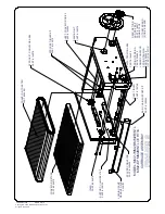
Remove the conveyor carriage and wash with warm soapy water and sanitize.
5.
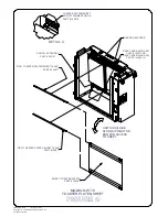
Check that the toaster platen sheet is installed under the contact platens. The toaster platen sheet is
installed by placing rods into arms of toaster. See Figure 4. Make sure seam is against platens (facing
top of toaster).
USE ONLY MARSHALL APPROVED PLATEN SHEETS OR TOASTER WARRANTY IS
VOID.
6.
Reinstall conveyor carriage and latch.
7.
Connect the toaster to the power supply.
8.
Press the on/off button and check for free movement of the two conveyor belts.
9.
Unit is ready to use in approximately 15 minutes.
10.
After warm up, insert buns into the toaster at the front of the unit. For proper operation, insert heels on the
side of the toaster marked "Heel", and crown on the opposite side.
THE CUT SIDES OF THE HEEL AND
CROWN MUST FACE UP.
11.
The toasted heel and crown will return to the toaster front together. Check the appearance of the toasted
buns.
12.
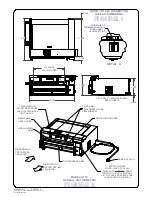
Adjust the gap between the conveyor and the toaster heat platens using the two knobs on top of the unit
(see Figure 2 for knob locations). Both must be lowered at the same time. The knobs are labeled “HEEL”
and “CROWN”. The height gauges in the front indicate whether you are raising or lowering the platens.
The Adjustment Ranges (except MM2B, G) are .625” – 1.438”. The MM2B, MM2BINTLCE, MM2G range
is .375” – 1.438”.
NOTE:
For
MM2B-ARB
Models: Start with Crown @6, Heel @3.5-4. See detail A in Figure 1 for
determination. Use the edge of the gauge metal not the scratched line from manufacturing.
13.
The conveyor speed is preset at the factory. The approximate adjustable speed ranges for the MM2A unit


