
I
nstallation of Recessed Back
Box in New Construction
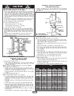
1. Mounting Back Box (See Figure 1).
a. Place the back box between two 16" (406 mm) center-to-center wall
studs at the desired mounting height but no closer than 8" (203 mm)
to adjacent wall or floor.
Note:
If wall studs are spaced greater than 16” on center, additional
framing supports may be necessary.
b. Align back box such that the bottom and sides will be flush with
finished wall surface (top flange of back box should protrude approxi-
mately 1/2" (12.7 mm) from finished wall surface).
c. Secure the back box in position with wood screws or nails as shown
in Figure 1.
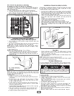
2. Power Supply Wiring (See Figure 1)
Note:
Wire compartment volume - 119in
3
(1950cm
3
).
a. Run a power supply cable into the knockout area in the upper right
hand corner of the back box. All wiring must be in accordance with
National and Local Electrical Codes. Refer to Table 1 for correct
wire size.
b. Remove disconnect switch bracket by loosening two screws on the
right side.
c. Install a cable clamp in the “knockout” in the top of the back box.
d. Insert power supply cable through cable clamp, allowing at least 6"
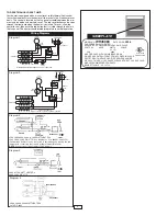
(152mm) of leads to extend inside the back box. Connect the blue
lead wires of disconnect switch to the supply wire leads using wire
connectors (see wiring diagram, pg. 4).
e. Ground the back box using the green screw located in the inside top
of the back box.
f. Secure disconnect switch bracket in place by tightening screws.
Installation of Recessed Back Box
in Existing Construction
1. Provide a wall opening 14-1/2" (362mm) wide by 18-1/2" (470mm) high
at the desired mounting height, but no closer than 8" (203mm) from floor.
(See Figure 2.)
Note:
Locate so at least one side of opening is at wall stud.
2. Power Supply Wiring
Note:
Wiring Compartment Volume - 119in
3
(1950cm
3
).
a. Run a power supply cable into the area above the top of the wall open-
ing. All wiring must be in accordance with National and Local electrical
codes. Refer to Table 1 for correct wire size.
b. Remove disconnect switch bracket by loosening the two screws on the
right side.
c. Install a cable clamp in the “knockout” in the top of back box.
d. Insert power supply cable through cable clamp, allowing approximate-
ly 6" (152mm) of cable length to remain inside the back box to facili-
tate connections.
3. Mounting Back Box
a. Place the back box into wall opening flush with finished wall surface on
bottom and sides of box. (Top flange of back box should protrude
approximately 1/2" or 12.7mm from finished wall surface).
b. Secure the back box in place with wood screws or nails.
4. Wiring Disconnect Switch
a. Connect the power supply wires to the blue wires of the disconnect switch
using wire connectors (see wiring diagram,pg. 4.)
b. Ground the back box using the green ground screw located in the
inside top of the back box.
c. Secure disconnect switch bracket in place by tightening screws.
CAUTION
FOR SAFE OPERATION AND REDUCED RISK OF FIRE, INJURY OR
HEATER DAMAGE, OBSERVE THE FOLLOWING:
1. Do NOT use a remote thermostat with this heater. Built in thermostat
cycles the heating element only. Fan delay control automatically turns
fan ON and OFF, and provides a fan delay OFF feature to remove
residual heat after thermostat has turned heating elements off. Wiring
of heater in any manner which defeats the fan delay OFF feature can
result in overheating and permanent damage to heater, and will void
the warranty.
2. For wall mounting only with air discharge downward. Do NOT install
in floor, ceiling, upside down (air discharge upward), or sideways.
3. Do NOT operate heater without grille installed.
4. Maintain the following clearances:
• Bottom of heater to floor – 8” (203mm)
• Sides of heater to adjacent wall – 8” (203mm)
• Top of heater to ceiling – 36” (915mm)
5. This heater is hot when in use. Do NOT install heater behind door,
behind towel rack, inside closet, where drapery could touch heater or
be damaged by heat, or where airflow to heater may be obstructed.
Keep electrical cords, bedding, furniture, and other items away from
heater.
6. Heater must be cleaned periodically (at least annually) to assure
proper performance and prevent overheating. See section on
cleaning and maintenance.
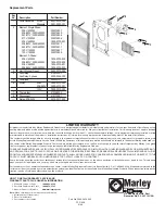
Fig. 1: Locating Back Box in New Construction
Fig. 2: Locating Back
Box in Existing Construction
!
8” (203mm) MIN
!
Back Box
Back Box
Table 1
Min.
Supply
Catalog
Wire
Number
Volts
Phase
Watts
Amps
Gauge
WH3150
120
1
1500
12.5
12
WH3180
120
1
1800
15.0
12
WH4404*
240/208
1
4000/3000 16.7/14.5
10
2000/1500
8.3/7.2
12
WH4407*
277/240
1
4000/3000 14.5/12.5
12
2000/1500
7.2/6.3
12
WH4307*
277
1
3000/1500
10.8/5.4
12
WH4408*
208
1
4000/2000
19.2/9.6
10
WH44083
208
3
4000
11.1
14
WH44043
240
3
4000
9.7
14
WH4303
347
1
3000
8.6
14
WH4306
600
3
3000
3
14
WH4508
208
1
4800
23.1
10
WH4504
208/240
1
3600/4800 17.3/20.0
10
WH4507
240/277
1
3600/4800 15.0/17.3
10
WH45083
208
3
4800
13.3
12
WH45043
240
3
4800
11.6
14
WH4503
347
1
4800
13.8
12
WH4506
600
1
4800
8
14
*NOTE: Factory wired for higher wattage, field convertible to half wattage.
2