background image


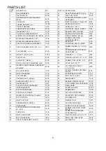
PARTS LIST 

PART 
NO, 

DESCRIPTION QTY 

PART 

NO, DESCRIPTION 


REAR STABILIZER 

1 PCS 

41 

REAR TRANSPARENT COVER 

1 PCS 

ADJUSTING CAP 

2 PCS 

42 

DISC FOR COVER 

2 PCS 

CARRIAGE BOLT FOR STABILIZER 
M8*75L 

4 PCS 

43 

FOAM GRIP FOR RIGHT & LEFT 
HANDLEBAR 

2 PCS 

ACORN NUT  

8 PCS 

44 

WAVY WASHER 

φ

17.5x

φ

25x0.3t  4PCS 

CURVED WASHER ( 

ø8*2t)


16 PCS 

45 

PEDAL ARM ( RIGHT ) 

1 PCS 

FRONT STABILIZER 

1 PCS 

46 

PEDAL ARM  ( LEFT ) 

1 PCS 

TRANSPORTATION WHEEL 

2 PCS 

47 

COMPUTER  CABLE   UPPER 

1PCS 

HANDLEBAR POST 

1 PCS 

48 

BEARING FOR FLYWHEEL 

1 PCS 

COVER FOR HANDLEBAR POST 

1 PCS 

49 

BUSHING FOR FLYWHEEL 

1PCS 

10 

SCREW FOR HANDLEBAR POST M8*16L  4 PCS 

50 

METAL BUSHING  38.

2

mm 

2PCS 

11 

MOVEABLE HANDLEBAR ( LEFT ) 

1 PCS 

51 

SCREWS FOR FIXING 
COMPUTER  M5*10L 

4PCS 

12 

MOVEAVLE HANDLEBAR ( RIGHT ) 

1 PCS 

52 

GEAR BOX 

1PCS 

13 

AXLE FOR MOVEABLE HANDLEBAR 

1 PCS 

53 

COMPUTER  CABLE  LOWER 

1PCS 

14 

TEFLON WASHER FOR MOVE( 

ø25*1t)


4PCS 54 

RUBBER SLEEVE 

ø2

6* 

ø3

2

*8.5L  

( A ) 

2PCS 

15 

FLAT WASHER ( 

ø10*2t)


4 PCS 

55 

SPRING WASHER FOR FIXING 
HANDLE BAR  

ø

8


4

PCS 

16 

HEX BOLT ( M8*P1.0*

20

L) 

2  PCS 

56 

WASHER 

ø17.5

ø25

*0.3L 

2PCS 

17 

PLASTIC CAP  

4 PCS 

57 

WASHER FOR DISC  

ø

5

ø

1

6

*

1

8PCS 

18 

ALLEN BOLT ( M8*55L) 

2 PCS 

58 

SCREWS FOR COVER    

3/16

” 

8PCS 

19 

NYLON  LOCK NUT


HANDLEBAR  ( 

M8

)


3

 PCS 

59 

NYLON  NUT  3/8”*7T 

2PCS 

20 

WASHER  FOR MOVEABLE HANDLEBAR 

φ

8x

φ

16x2t 

4 PCS 

60 

CAP FOR PEDAL ARM  

ø3

ø32*

13.5L (B) 

2PCS 

21 

LEFT HANDLEBAR 

1 PCS 

61 

SPRING  WASHER FOR PEDAL 
ARM 

ø

4PCS 

22 

RIGHT HANDLEBAR 

1 PCS 

62 

ACROSS BAR FOR DISC 

2 PCS 

23 FLAT 

WASHER 

1

 PCS 

63 

BIG  PULLEY  

ø

289*9


1 PCS 

24 

CARRIAGE BOLT  ( M8*40L) 

4 PCS 

64 

DRIVING BELT 

1 PCS 

25 

ALLEN HEAD BOLT (

M8*35L)


4 PCS 

65 

BERAING FOR BIG PULLEY 

2 PCS 

26 

HANDPULSE SET 

1 SET 

66 

C TYPE RING FOR ACROSS BAR  1 PCS 

27 

FOAM FOR FIXED HANDLEBAR 

1 PCS 

67 

MAIN FRAME 

1 PCS 

28 

FIXED HANDLEBAR 

1 PCS 

68 

SCERW FOR DISC 

14 PCS 

29 

NUT FOR PEDAL ARM 

2 PCS 

69 

SENSOR BOX 

1 PCS 

30 

SCRW FOR FLYWHEEL 

1 PCS 

70 

NUT FOR ACROSS BAR 

2 PCS 

31 

WASHER FOR FLYWEEL

φ

10x

φ

18x1t 

2 PCS 

71 

ADJUSTOR FOR FLYWHEEL 

2 PCS 

32 

LEFT FOOT PAD 

1PCS 

72 

FLYWHEEL SET 

1 SET 

33 

RIGHT FOOT PAD 

1 PCS 

73 

MAGNETIC SET 

1 SET 

34 

CARRIAGE BOLT ( M6*50L) 

4 PCS 

74 

CAP FOR PEDAL ARM 

2 PCS 

35 

FIXING KNOB 

4 PCS 

75 

SCRWS FOR COVER  M4x50L 

2 PCS 

36 

FLAT  WASHER FOR FIXING KNOB 

ø

6* 

ø1

6*2t 

4 PCS 

76 

SCREWS FOR FIXING COVER 
(M4*20L) 

2 PCS 

37 COMPUTER 

PCS 

77 

SCREW FOR FIXING REAR 
COVER (M4*12L) 

6 PCS 

38 

RIGHT CHAINCOVER 

1 PCS 

78 

WAVY WASHER (

ø

20

ø3

0

*

0.3T

1 PCS 

39 

LEFT CHAINCOVER 

1PCS 

79 

SMALL DISC FOR COVER 

2 PCS 

40 

FRONT TRANSPARENT COVER 

1 PCS 

80 

AC ADAPTOR 

1 PCS 


Содержание E7000D

Страница 1: ...IPTICAL TRAINER PRODUCT CODE E7000D Escalade International Limited Pleasant Road Penllergaer Swansea SA4 9GE Tel 00 44 1792 222 550 Fax 00 44 1792 895 781 www escaladesports co uk info escaladesports co uk ...

Страница 2: ...er guide 12 Computer 13 Principles of Exercise 15 Fault Finding Chart 17 Additional Information 17 Warranty Ordering Parts 18 Maintenance Specifications 18 Supplied by Escalade International Ltd Pleasant Road Penllergaer Swansea SA4 9GE Tel 00 44 1792 222550 Fax 00 44 1792 895781 www escaladesports co uk E mail info escaladesports co uk ...

Страница 3: ...o use the Elliptical their physical mental development and above all temperament should be taken into account Constant supervision is therefore needed 6 Position the Elliptical on a clear levelled surface which is clear of all obstacles as not to restrict movement whilst exercising DO NOT use the Elliptical near water or outdoors 7 Exercise equipment has moving parts In the interest of safety keep...

Страница 4: ...lliptical in accordance with the steps in the manual Box spanners and an allen key are included for assembly Lay out all parts on the floor Make sure that you have all the parts listed below before beginning assembly In case of discrepancy please call our Customer Service Department at the number listed on page 18 of this manual OUR ELLIPTICALS ARE MANUFACTURED WITH CARE AND ATTENTION QUALITY AND ...

Страница 5: ...EXPLODED DIAGRAM 5 ...

Страница 6: ...5L 2 PCS 58 SCREWS FOR COVER 3 16 8PCS 19 NYLON LOCK NUT HANDLEBAR M8 3 PCS 59 NYLON NUT 3 8 7T 2PCS 20 WASHER FOR MOVEABLE HANDLEBAR φ 8xφ16x2t 4 PCS 60 CAP FOR PEDAL ARM ø3 ø32 13 5L B 2PCS 21 LEFT HANDLEBAR 1 PCS 61 SPRING WASHER FOR PEDAL ARM ø6 4PCS 22 RIGHT HANDLEBAR 1 PCS 62 ACROSS BAR FOR DISC 2 PCS 23 FLAT WASHER 1 PCS 63 BIG PULLEY ø289 9 1 PCS 24 CARRIAGE BOLT M8 40L 4 PCS 64 DRIVING BE...

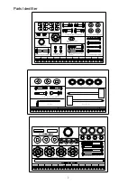
Страница 7: ...andlebar M8 35 4 NO 34 Carriage Bolt M6 foot pedal 4 NO 60 Rubber cap for pedal arm 1 N O 1 7 P la stic ca p fo r M 8 n u t 4 N O 1 4 T e flo n w a sh e r 3 A lle n K e y 1 B o x S p a n n e r 2 N O 2 4 C a rria g e B o lt M 8 4 0 h a n d le b a r 4 7 NO 44 Spring Washer 3 NO 15 Flat Washer for M10 bolt movable handlebar 3 NO 20 Flat Washer 16mmdia for M8 bolt 4 NO 35 Knob M6 P1 0 foot pedal 4 NO ...

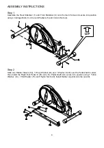
Страница 8: ...Carriage Bolts 3 4 Curved Washers 5 and 4 Acorn Nuts 4 Step 2 UP Slide one Rubber Sleeve 54 1 Wavy Washer 44 and 1 Washer 46 over the Pedal shaft in order then install the Right Foot Pedal 45 onto the Pedal shaft and secure into position using 1 Teflon Washer 14 1 Flat Washer 15 and 1Nylon Nut 49 Install Rubber cap 60 onto the nut 49 8 ...

Страница 9: ...n the Allen Head Bolts at this stage Step 4 Insert Axle 13 through the bushing welded to the Handlebar Post Slide 1 Wavy Washer 44 onto each end of the axle Assemble the Left and Right Movable Handlebars 11 12 onto the Axle and secure using 2 Teflon Washers 14 2 Flat Washers 15 and 2 Hex Bolts with blue dots 16 Install Nut Caps 17 onto the Hex Bolts Note 1 The Pedal arms are marked with L left and...

Страница 10: ...r and Left Pedal Arm Fully tighten the 2 nuts and bolts Install Nut Caps 17 onto Nuts 19 Tighten the 4 bolts previously installed in Step 3 Step 6 Install the Left Handlebar 21 onto the Left Moveable Handlebar 11 and secure using 2 Carriage Bolts 24 2 Curved Washers 5 and 2 Acorn Nuts 4 Repeat the above procedure for the Right Handlebar 22 Step 7 Assemble the Fixed Handlebar 28 onto the Handlebar ...

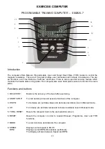
Страница 11: ...xing Knobs 35 Repeat the above procedure for the Right Foot Pad 33 Step 9 Connect the Computer Cable Upper 47 into the rear of the computer Position the Computer on top of the Handlebar Post and secure into position using 4 Screws 51 Connect the Sensor Wire from the Fixed Handlebar into the rear of the Computer marked PULSE INPUT 11 ...

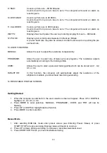
Страница 12: ...PS on the REAR STABILIZER BAR By rotating these end caps you should be able to level the Elliptical on any floor surface 12 STORING THE ELLIPTICAL TRAINER The caps at each end of the FRONT STANLIZER BAR on your ELLIPTICAL TRAINER are also transport wheels You can use these wheels to easily move the ELLIPTICAL TRAINER from place to place Insert Adaptor Here ...

Страница 13: ...he users pulse Functions and buttons 1 RECOVERY Monitors the recovery of the heart after exercising 2 START STOP To start and stop time and exercise functions of the computer 3 DOWN To decrease pre set data values and decrease resistance level in Manual mode 4 UP To increase pre set data values and increase resistance level in Manual mode 5 TOTAL RESET Resets the computer back to the user selectio...

Страница 14: ...twelve pre set programs The resistance adjusts automatically according to the training profile USER Allows the user to enter a personal training profile which can be stored as U1 U2 U3 or U4 TARGET HR In this function the computer will automatically adjust the resistance of the elliptical to maintain your ideal heart rate during exercising 14 RESISTANCE PROFILE SCREEN Getting Started 1 When the co...

Страница 15: ...p 4 Press START STOP when you have finished exercising Entering Preset Data 1 Press MODE TIME will begin Flashing 2 Press UP or DOWN buttons to increase or decrease time 3 Press MODE to highlight functions of DIST CALORIES or PULSE and enter preset values Preset values may be entered for all functions or only one function 4 Press START STOP to begin exercising Preset values will begin to count dow...

Страница 16: ...nd continuous nature Running swimming stair climbing cycling brisk walking etc are all examples of aerobic exercise It is recommended that the average healthy adult perform aerobic exercise for a minimum of 20 to 30 minutes three times per week at an intensity that elevates the heart rate to within the Target Heart Rate Zone The Target Heart Rate Zone is between 70 and 85 of the Age Predicted Maxi...

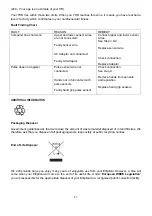
Страница 17: ...nds not in full contact with pulse sensors Faulty hand grip pulse sensor Check connection See step 9 Remove hands from sensors and reposition Replace hand grip sensors ADDITIONAL INFORMATION Packaging Disposal Government guidelines ask that we reduce the amount of waste material disposed of in land fill sites We therefore ask that you dispose of all packaging waste responsibly at public recycling ...

Страница 18: ... damage to a product caused by or attributable to freight damage abuse misuse improper or abnormal usage purchasers own repairs or for products used for commercial or rental purposes No other warranty beyond that specifically set forth above is authorized by Escalade Escalade is not responsible or liable for indirect special or consequential damages arising out of or in connection with the use or ...

Отзывы: