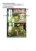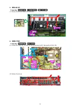
(2) Remove the connector wire and STYLE PIN.
(3) Remove the screws.
NOTE : It will separate and TRANS will fall from SET, if screws is removed.
8. SMPS PCB
Proceeding :
TOP COVER
→
SMPS PCB
(1) Remove the connector wire. Remove the screws.
See "
EXPLODED VIEW
" for instructions on how to remove each PCB of the "
SMPS PCB
".
CP4401
STYLE
PIN
View from the bottom
18
Содержание NR1605/FB
Страница 8: ...Personal notes 8 ...
Страница 26: ...Personal notes 26 ...
Страница 103: ...CX870 7P 8P 5P PLATE PLATE 2P 7P 4P 7P 11P 5P 8P PLATE S30SC6MT WIRING DIAGRAM 103 ...
Страница 140: ...Personal notes Personal notes 140 ...
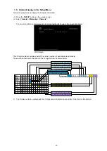
Страница 161: ...2 FL DISPLAY FLD 018BT021GINK FRONT U4400 PIN CONNECTION GRID ASSIGNMENT q T7 161 ...
Страница 162: ...ANODE CONNECTION 162 ...


