Marantz Icemaker Скачать руководство пользователя страница 37

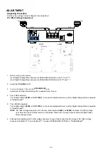
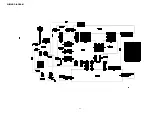
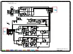
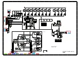
8U-310151 (DIGITAL PCB) (A side)       

q

R859

y

R867

Q1

R822

w

R858

u

R827

Q2

R823

e

R871

i

R825

r

R449

o

R826

t

R450

Q0

R824

PR

OT2

VOL

TAGE

PROT

PR

OT1

G

OUT

VCC

A

1

19

W

1

12

115X160

63301015110AM

8U-310151

A

A

B

B

C

C

U304

K301

N401

N801

B101

B102

B301

B302

N101

N102

N103

N104

N105

N301

N701

C372

B400

B401

N110

R400 R401

R402

R405

R406

R408

R409

R410 R411

R412

R414

U101

R415

R416 R417

R419

R807

R808

R420

U301

R809

U302

U303

R423

U305

U306

U307

U308

R810

R428

U309

R811

R429

R812

R813

R430

R431

R432

R433

R434

R435

R436

R437

U700

R438

U701

R439

R822 R823 R824

C400

R825

C401

R826

C402

R827

C403

R828

R440

C404

R829

R441

C405

R442

C406

R443

C407

R444

C408

C409

R445

R446

R447

R830

R448

R449

R834

C410

X400

C411

R836

C412

R837

C413

R838

C414

R450

R839

R451 R452

R453

R454

C418

R455

C419

R840 R842

R843

R844

C420

R845

R846

C422

R847

R848

R461

R849

C425

C426

C427

R464

C428

R850

R851

R852

R853

R854

C431

R857

R470

R858

R859

R474

R475

R860

C825

C826

C827

C828

R864

C829

R866

R867

R868

R480

R869

R481

R482

R483

R484

R485

R486

R487

R870

Q101

R871

Q102

C836

R872

Q103

C837

R873

Q104

C838

R874

Q105

R875

C839

C451

Q106

R876

Q107

R877

Q108

R878

R490

Q109

R491

R492

R493

R494

Q301

R495

Q110

R880

Q111

R881

Q112

Q113

R883

Q114

R884

D400

Q115

L101

D401

Q116

L102

D402

L103

Q117

Q118

L105

L106

L109

L301

L302

R893

L110

Q701

C472

Q703

R897

Q704

Q705

C476

Q706

D800

D801

D802

L700 L701

L702

L703

L704

L705

C492

C493

C494 C495

C496

C497

C498

C499

R101

R102

R103

R104

R105

R106

R107

R108

R109

R302R303

R304

R111 R112

R307

R113

R308

R114

R115

R309

R116

R117

R118

R119

R310 R311 R312 R313 R314

R315

R121

R122

R316

R317

R124

R318

R319

R126

R702

R708

R320

R709

R321

R322

R323

R324

R900

R325

R901

R326 R327

R903

R710

R134

R328

R904

R135

R329

R711

R136

R906

R713

R137

R907

R714

R138

U400

U401

U402

U403

U404

R330

R331

C101 C102

C103

C104

R910

C105

R911

C106

R912

C107

C108

C109

R146

R147
R148

C301

R149

C302 C303

C110

C304

C111

C305

X101

R341

C112

C306

R343

C113

C307

C114

C308

R150

U800

R151

R345

C115

C309

U801

R152

C116

R346

R153

C117

R347

R348

C500

C118

U804

C501

C119

U805

R349

R156

R927

C310

C311

C312

C313

C120

R350

C121

R351

C122

R352

C123

R160

C124

C318

C700

C125

C319

R161

R355

C701

C126

R162

R356

C702

R357

C127

R163

C703

R164

C128

R934

R358

C704

R165

R359

C129

R935

C705

R166

C706

R167

C707

R937

R938

C320

C708

R168

R939

C321

C709

R169

C322

C323

C324

C130

R360

C131

C325

R361

R362

C132

C326 C327

R363

C133

R940

C328

R364

C710

R170

R941

C135

C711

R365

R171

R942

C712

R366

R172

R943

C137

C713

R367

R173

R944

C714

R174

R175

R945

C715

R176

R946

C716

R177

R947

C717

R178

R948

C718

C330

R179

C719

R949

C331

C333

R370

C140

R371

C141

C335

R372

C336

R373

C337

C143

R374

R950

C338

R375

R951

C339

R376

R952

C146

R377

R953

C724

R378

R954

C725

R379

C726

C727

C728

C729

R380

C344 C346

C348

C349

C733 C734 C735

C736

C737

C738

C350

C351

C352

C353

C354

C355

D101

D103

C359

C742

C743

C744

C748

C360

C749

C361

D301

C362

D302

C363

C364

Q400

C365

C366

Q403

C367

C750

C368

C369

C751

C370

C371

C373

L400

D701

L401

D702

L402

D703

D704

D705

L405

L406

C381

C382

C383

C384

C385

C386

L800

L801

DIP

1

REF

A

w

q

e

y

u

io

Q0

Q1Q2

r

t

37

Содержание Icemaker

Страница 1: ...s reserved WARNING Violators will be prosecuted to the maximum extent possible Ver 3 Some illustrations using in this service manual are slightly different from the actual set Please use this service...

Страница 2: ...EDURE AFTER REPLACING THE MICROPROCESSOR ETC 22 FIRMWARE UPDATE PROCEDURE 22 ADJUSTMENT 30 TROUBLE SHOOTING 32 1 The power can not be turned on 32 2 The power can not be turned on 32 3 STANDBY LED FLA...

Страница 3: ...ice manual What you can do with this manual Search for a Ref No phrase Ctrl Shift F You can use the search function in Acrobat Reader to search for a Ref No in schematic diagrams block diagrams and pa...

Страница 4: ...Adobe Reader 9 On the Document menu click Sign Magnify schematic printed wiring board diagrams 1 Ctrl Space mouse operation Press Ctrl Space on the keyboard and drag the mouse to select the area you...

Страница 5: ...en Example using Adobe Reader 9 On the Tools menu point to Select Zoom and then click Pan Zoom Window Magnify schematic printed wiring board diagrams 3 Loupe Tool function The Loupe Tool function lets...

Страница 6: ...tant safety parts that are indicated by the z mark on schematic diagrams and parts lists be sure to use the designated parts Be sure to mount parts and arrange the wires as they were originally placed...

Страница 7: ...problem is identified and remedied NOTICE ALL RESISTANCE VALUES IN OHM k 1 000 OHM M 1 000 000 OHM ALL CAPACITANCE VALUES ARE EXPRESSED IN MICRO FARAD UNLESS OTHERWISE INDICATED P INDICATES MICRO MIC...

Страница 8: ...Personal notes 8...

Страница 9: ...NO MM 2 0 mV 47 k kohms CD TUNER NETWORK RECORDER 200 mV 20 k kohms Maximum allowable PHONO input level 1 kHz MM 100 mV RIAA deviation 20 Hz 20 kHz 0 5 dB S N IHF A 8 ohms load PHONO MM 85 dB 5 mV inp...

Страница 10: ...166 1k ohm This resistance is set for the destination settings and uses the default value of Auto Standby mode N Region Tuning Auto Standby mode OFF by default F U K Region Tuning Auto Standby mode OF...

Страница 11: ...ef No of EXPLODED VIEW P6 POWER SW PCB Ref No of EXPLODED VIEW P10 TOP COVER TRANS POWER See DISASSEMBLY 7 TRANS POWER and EXPLODED VIEW MAIN TRANS Ref No of EXPLODED VIEW T0001 HEAT SINK ASSY See DIS...

Страница 12: ...iagram below about the shooting direction of each photograph Photographs with no shooting direction indicated were taken from the top of the set The photograph is PM7005F The viewpoint of each photogr...

Страница 13: ...TOP COVER FRONT PANEL ASSY 1 Remove the nut the washer and screws 2 Cut the wire clampers and remove the connector wires Remove the screws View from the bottom TOP bottom NUT and WASHER N8502 N2802 N...

Страница 14: ...2 HEAT SINK ASSY Proceeding TOP COVER HEAT SINK ASSY 1 Cut the wire clamper and remove the screws Remove the connector wires N7501 N8001 N7002 N7001 N9002 CUT 14...

Страница 15: ...3 DIGITAL PCB Proceeding TOP COVER DIGITAL PCB 1 Remove the connector wires Remove the screws 2 Remove the screws N101 N701 N301 N105 N104 N102 CUT 15...

Страница 16: ...ceeding TOP COVER DIGITAL PCB PHONO HDAM PCB 1 Remove the screws Remove the connector wires 5 MAIN PCB Proceeding TOP COVER DIGITAL PCB PHONO HDAM PCB HEAT SINK ASSY MAIN PCB 1 Remove the screws N4002...

Страница 17: ...the connector wires Remove the screws 7 TRANS POWER Proceeding TOP COVER TRANS POWER 1 Cut the wire clamper and remove the connector wires Remove the screws N8501 N8507 N8503 N8505 N8502 STYLE PIN PC...

Страница 18: ...on the front LED Display time is only for 3 seconds Lighting position is same as firmware version 5 Each LED light up then all LED light up 6 Turn off the power to quit Service Mode The unit to the d...

Страница 19: ...peration results in after this depends on how long the signal from the PROT_1 has to remain Lo If the PROT_1 pin26 recovers to Hi within as short a period of time as one second or less The MUTE indica...

Страница 20: ...80mA Q8015 and Q9001 will turn on to change the signal from the PROT_2 pin24 to Lo from Hi If any of the above three abnormalities is detected the signal from the P_ON pin78 terminal will be changed t...

Страница 21: ...ected the signal from the P_ON pin78 terminal will be changed to Lo from Hi the power relay S8501 will be turned off and the unit will be shut down Then the STANDBY indicator flickers and indicates th...

Страница 22: ...itten by version updates Check the version C The software has not been written The software needs to be written after replacement See Firmware Update Procedure for information on writing the software...

Страница 23: ...G KIT to the update terminal of the unit 1 Prepare the windows PC that installed the FLASHSTA EXE 2 Connect SPK 581 as follows 3 Double click the FLASHSTA EXE And launch the M16 Flash Start PC Connect...

Страница 24: ...4 Check the Internal fash memory in the Select Program Choose the COM Port number And click the OK 5 Click the Refer 24...

Страница 25: ...Select the file and click the OPEN 7 The FilePath and ID are inputted automatically and the MCU Type is selected toM16C 20 62 automatically Click the OK PM7005_XXXXXX mot PM7005_Software PM7005_XXXXXX...

Страница 26: ...lick the Setting 9 Choose the 57600 in the Baud rate DO NOT choose the other one Click the OK b The setting is memorized if it does once It is necessary to set it to connected failure again when doing...

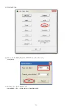
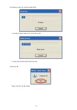
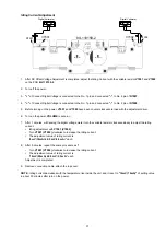
Страница 27: ...10 Click the E P R 11 Click the OK 27...

Страница 28: ...oftware is written into the Internal Flash ROM The writing of software takes about 1 minute 30 seconds The checking of software takes about 50 seconds 13 Click the OK Please retry it from 8 when faili...

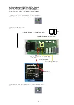
Страница 29: ...14 Click the Exit 15 Remove the AC plug for power off this unit 16 Remove the SPK 581 form this unit 29...

Страница 30: ...djusted to 0 mV 3 mV 5 Then R CH is adjusted The variable resistor V6002 on 8U 110159 1 is turned with adjustment driver and the Digital Voltage Meter is adjusted to 0 mV 3 mV NOTE DC offset voltage d...

Страница 31: ...meter turn the variable resister clockwise slowly to adjust the idling current Idling adjustment with V7001 V7002 Turn V7001 V7002 clockwise to increase the idling current The adjustment value of idl...

Страница 32: ...plied Power supplied Power not supplied Power supplied Check whether power is being supplied to the F8520 Check each connector Check whether power is being supplied to the coil of the MAIN TRANS Check...

Страница 33: ...returns to normal operation Check input level and each connector Check each connector Broken wire in MAIN TRANS Damaged power amplifier circuit Damaged Selector U3903 S3001 Q3045 Tone Circuit S2801 S2...

Страница 34: ...U 310151 DIGITAL PCB Check the AUDIO DATA CLK Check input and output the U309 DAC R362 R365 U309 23 24 pin 19 20 pin WCK BCK PCM_DATA_L R Is the U0800 64 pin R0869 Lo Is the U0800 85 pin R0839 Lo Cont...

Страница 35: ...CK LRCK clock 32KHz 192KHz R0445 USBB_BCK BCK clock 2 112MHz 12 288 MHz R0447 USBB_DATA PCM data Check 5 8U 310151 DIGITAL PCB DIR BLOCK Check Power Supply DIR and if there are no problems check or re...

Страница 36: ...8 C700 C125 C319 R161 R355 C701 C126 R162 R356 C702 R357 C127 R163 C703 R164 C128 R934 R358 C704 R165 R359 C129 R935 C705 R166 C706 R167 C707 R937 R938 C320 C708 R168 R939 C321 C709 R169 C322 C323 C32...

Страница 37: ...R105 R106 R107 R108 R109 R302 R303 R304 R111 R112 R307 R113 R308 R114 R115 R309 R116 R117 R118 R119 R310 R311 R312 R313 R314 R315 R121 R122 R316 R317 R124 R318 R319 R126 R702 R708 R320 R709 R321 R322...

Страница 38: ...5N 58pin DIR1_LRCK eR871 EPM240T100C5N 61pin DIR1_DATA yR867 EPM240T100C5N 67pin USBB_DSD_BCK rR449 EPM240T100C5N 68pin USBB_DSD_DATA_L tR450 EPM240T100C5N 69pin USBB_DSD_DATA_R uR827 EPM240T100C5N 34...

Страница 39: ...Personal notes 39...

Страница 40: ...CD etc 200mV 14 0dB Digital in 22 5dBFS PCM 18 6dBFS DSD MM 2mV 54 0dB 60W 8 21 9V 26 8dB 30 30 40 50 60 70 dB 20 20 10 10 0 30 30 40 50 60 70 dB 20 20 10 10 0 40 0dB 16 8dB 24 0dB LEVEL DIAGRAM 40...

Страница 41: ...RECORDER 1 IN RECORDER 1 OUT SPEAKER SPEAKER HEADPHONE VOLUME BALANCE SOURCE DIRECT MUTE CD DIRECT CD DIRECT BUFFER LINE BUFFER REC BUFFER BASS LINE DETECT LINE DETECT AMP USB Type B COAXIAL OPTICAL...

Страница 42: ...RC5 STANDBY LED STANDBY RELAY POWER ON OFF SW STANDBY RELAY FUSE MAIN TRANS SUB TRANS 5V INDICATOR LED 3 3V COM 5V 5V DAC 3 3V DAC 1 8V USB DAC 3 3V 1 2V USB DAC USB DAC DIR PLD etc 28V 24V 9V 7V AC I...

Страница 43: ...WIRING DIAGRAM 43...

Страница 44: ...N2801 R6015 N2802 R6016 R6017 R6018 R6019 R3909 F8300 D6020 D6021 D6022 D6023 D6024 R6020 R3910 R6021 R3911 R6022 R3912 R6023 R3913 R6024 R3914 R6025 R3915 R6026 R6027 R6028 R6029 R3919 12 5 JV102 JV...

Страница 45: ...S1251 1 C1251 Q1251 Q1252 D1251 D1252 D1253 D1254 R1251 D1255 R1252 D1256 R1253 D1257 R1254 D1258 R1255 D1259 R1256 R1257 R1258 R1259 D1260 D1261 D1262 R1260 R1261 R1262 R1263 R1264 R1265 R1266 R1267...

Страница 46: ...C303 C110 C304 C111 C305 X101 R341 C112 C306 R343 C113 C307 C114 C308 R150 U800 R151 R345 C115 C309 U801 R152 C116 R346 R153 C117 R347 R348 C500 C118 U804 C501 C119 U805 R349 R156 R927 C310 C311 C312...

Страница 47: ...21 C4522 Q4520 Q4521 Q4522 Q4523 Q4524 R4501 R4502 R4503 R4504 L4001 R4505 L4002 R4506 R4507 R4508 R4509 R4510 R4511 R4512 R4513 R4514 R4515 R4516 R4517 R4518 R4519 R4520 R4521 R4522 R4523 R4524 R4525...

Страница 48: ...KSA992FTA R3059 22 Q3011 KSC1845FTA R3058 22 R3049 22 R3047 470 R3052 22 Q3013 KSC1845FTA R3060 22 R3054 15K Q3012 KSC1845FTA R3048 470 Q3016 KSA992FTA R3053 15K R3043 220K R3055 15K A GND 00M5110030...

Страница 49: ...8GR Q6036 KTC3198GR Q6028 KTC3198GR Q6025 KTC3198GR Q6026 KTC3198GR Q6027 KTC3198GR Q7002 2SC4495 R7018 220 R7017 220 N7005 1 2 3 4 5 6 N7003 1 2 3 4 5 6 N7004 1 2 3 4 5 6 N7006 1 2 3 4 5 6 Q9503 2N55...

Страница 50: ...C4000 0 1Z R4007 33 R4008 33 R4003 100K R4004 100K C4004 220P C4003 220P R4005 100K R4006 100K C4017 OPEN R4009 82 R4010 82 R4011 82K R4012 82K C4018 OPEN R4022 10 R4021 10 9P EH N4001 1 PHONO R 2 A_G...

Страница 51: ...R2706 S2702 3 9K R2705 S2701 3 9K R2704 0 01 C2702 3 9K R2703 S2704 2 2K R2702 3 3VL D GND 100 10 C2603 SHORT R2601 0 01 C2602 OPEN C2601 R34ES9A 15MM 36KHZ U2601 2 GND 3 VCC 1 VOUT 100 R2602 3 3VL 0...

Страница 52: ...56 Z5902 RETAINER C5901 OPEN 13P SOCKET C125Z2 N5902 13 12 11 10 9 8 7 6 5 4 3 2 1 9999999999_89 OPEN Z5901 N5901 3P EH IM 1 MOT 2 3 MOT 0 01 C5902 N7503 3P EH IM 1 2 3 C7512 OPEN 00D2050452017 Z7511...

Страница 53: ...IN 6 GND 7 CNVSS 8 CTL_ 3 3USBB 9 VTL_ 1 8USBB 10 RESET 11 XOUT 12 GND 13 XIN 14 VCC 15 NMI 16 NC 17 DIR1_CFLUG 18 P_DOWN 19 SPK_OUT 20 CONT5 21 INT 22 STB_LED 23 USBB_DSD_PCM 24 PROT_2 25 VOLTAGE_PRO...

Страница 54: ...1 100 R347 GND_A 10K R357 R363 56 GND 0 1 C335 OPEN R348 0 1 C338 100 R352 R360 0 GND_A C369 0 1 U309 CS4398 CZZR 1 NO_USE 28 NO_USE 27 VLS 26 VQ 25 BMUTE 24 AOUTA 23 AOUTA 22 VA 21 AGND 20 AOUTB 19 A...

Страница 55: ...I H18 GND H19 RTC_XO J1SATA_Tx_P J2 SATA_Tx_N J3 IN OUT02 J4 IN05 J5 DVDD3318_C J6 CVDD J7 GND J9 GND J10 GND J11 GND J12 CVDD J13 DVDD18 J14 DVDD3318_B J15 TCK J16 EMU0 J17 NMIn J18 TDO J19 RTC_XI K1...

Страница 56: ...C704 0 1Z C705 0 1Z C701 0 01Z C702 1000P 0 R708 33_VCC_USB_B 0 R704 0 R706 0 R707 0 R705 GNDUSBB 0 R709 0 R710 4P EHs N701 1 2 3 4 5V DIG CLT_M INPUT 0 01Z C737 0 1Z C722 33_VCC_DIR 0 1Z C714 47P C71...

Страница 57: ...C817 0 1Z C821 0 1Z C809 0 1Z C807 0 1Z C824 0 1Z C801 0 1Z C805 0 1Z C819 0 1Z C823 0 1Z C803 0 1Z C811 0 1Z C815 0 1Z C813 0 1Z 1SS355T D800 1SS355T D801 1SS355T D802 56 R897 56 R860 56 R850 56 R90...

Страница 58: ...TITE SCREW W FLAT WASHER 9 S5 00M51270308M0 B H TAP TITE SCREW W 3 Points Notch 11 S6 00M51280308M0 B H TAP TITE SCREW B TYPE Copper 43 S7 00M51280308U0 B H TAP TITE SCREW B TYPE Black 4 S8 00M5128031...

Страница 59: ...e see the last chapter for the part list 0020U 0040P 0060P 0060P 0040P 0010P 0050P 0020A 0030A 0010U 0060U 0020U 0050U 0030U 0010A 0020P 0020P 0070P x4 0022P UK plug UK Only 0080P W0001 58 PACKING VIE...

Страница 60: ...Chg No Chg Q7 No Chg 1 1 0 0 QN 1 Q7 No Chg 1 1 1 1 QN 1 Q7 No Chg 1 1 1 No Chg No Chg No Chg Q7 Z High Impedance X Don t Care At the positive clock edge information in the 7th shift register stage is...

Страница 61: ...t 5 Q2 O O P DIRECT H L PD 10k Power Amp direct in Relay ON ON H 6 Q3 O O CD H L PD 10k CD Input Relay ON ON H 7 Q4 O O LINE H L PD 10k LINE Input Relay ON ON H 8 VSS GND GND 9 QS O O QS Open 10 Q S O...

Страница 62: ...S0 P64 CTS1 RTS1 CTS0 CLKS1 P8 2 INT 0 P8 3 INT 1 P8 5 NMI P97 ADTRG SIN4 P44 CS0 P50 WRL WR P51 WRH BHE P9 0 TB0 IN CLK3 P8 4 INT 2 P72 CLK2 TA1OUT V P71 RxD2 SCL2 TA0IN TB5IN Note P70 TXD2 SDA2 TA0O...

Страница 63: ...1 I Protection1 DC Offset Over Current Heat 27 P7_1 RXD2 SCL2 TA0IN TB5IN OD BE_FL_DT I NC 28 P7_0 TXD2 SDA2 TA0OUT OD NC O L 29 P6_7 TXD1 SDA1 TXD O L Update 30 P6_6 RXD1 SCL1 RXD I Update 31 P6_5 C...

Страница 64: ...0_6 D6 USBB_44_48 I for USB B 81 P0_5 AN0_5 D5 DESTINATION_SEL I Destination selector H L N F U K 82 P0_4 AN0_4 D4 VOL_UP O Hi Z Volume up 83 P0_3 AN0_3 D3 VOL_DOWN O Hi Z Volume down 84 P0_2 AN0_2 D2...

Страница 65: ...TC7WHU04FU DIGITAL U301 U303 U804 U805 65...

Страница 66: ...PCM9211 DIGITAL U302 PCM9211 Block Diagram 66...

Страница 67: ...PCM9211 Pin Discriptions 67...

Страница 68: ...Control 8 IO MODE2 CD MECHA IN MP3 fs 44 1k 48k L 32k H Detect 9 VCCIO1 33_VCCIO DA3 3V Power Supply 10 GNDIO GND DGND Ground 11 GNDINT GND DGND Ground 12 IO GCLK0 FE_DSD PCM CD MECHA IN MODE FE_DSD...

Страница 69: ...V3 51 IO PLD_DAC_SEL AUDIO UNIT SELECTOR OUT PLD_DAC_SEL 52 IO DAC_CK_IN M3062LFGPGP IN DAC_CK_IN for L Rch DAC to DSD1792A MC 53 IO DAC_CS_IN M3062LFGPGP IN DAC_CS_IN for L Rch DAC to DSD1792A MS 54...

Страница 70: ...ers Lo Detect 86 IO CONT5 M3062LFGPGP IN MCK USB A Others Detect 87 IO CLK22 5792Mhz AK8142 OUT AK8142 22 5792MHz 88 IO SLAVE_ MCK_33 8688M AK8142 IN AK8142 MCK 33 8688MHz 89 IO OCXO_IN_22 5792M AK814...

Страница 71: ...CS2000 CP DIGITAL U801 CS2000 CP DIGITAL U3914 Block Diagram 71...

Страница 72: ...TC74LCX157FT DIGITAL U307 U308 72...

Страница 73: ...the internal sampling circuits BMUTEC AMUTEC 18 25 Mute Control Output The Mute Control pin is active during power up initialization mut ing power down or if the master clock to left right clock frequ...

Страница 74: ...7002 00D2730445001 2SC4495 00D2730445001 1 Q7003 7004 00D2730471907 KTC3206 Y AT P 00D2730471907 1 Q7005 7006 00D2710314903 KTA1024 Y AT P 00D2710314903 1 Q7007 7008 21305001420AS KTC3423 Y U PH 2130...

Страница 75: ...5 00D2412400953 1 R6045 6048 nsp RD14B2E220JT 5 00D2412394962 1 R6049 6050 nsp RD14B2E104JT 5 00D2412403934 1 R6051 6054 nsp RD14B2E220JT 5 00D2412394962 1 R6055 6056 nsp RD14B2E104JT 5 00D2412403934...

Страница 76: ...E104ZT 1608 00D2570512903 1 C8309 nsp CK73B1H103KT 1608 1608 00D2570501901 1 C8310 13305030640AS CQ93P2A103JT DTN 13305030640AS 1 Ver 3 C9001 00D2544573949 CE04W1H010MT RA3 00D2544573949 1 C9002 00MOA...

Страница 77: ...690192902 1 Q4801 00D2757001907 FDC608PZ 00D2757001907 1 Q8501 00D2690192902 KRC102S RTK P 10K 10K 00D2690192902 1 Q8502 00D2730464901 KTC3875S GR RTK P 00D2730464901 1 Q8530 00MHT348832A0 TRANSISTOR...

Страница 78: ...2W 00MNK05331020 1 R8501 00MGG0522016X 22 OHM 5 1 6W 00MGG0522016X 1 R8502 nsp RM73B 823JT 1608 00D2472012909 1 R8503 8504 nsp RM73B 472JT 1608 1608 00D2472009909 1 R8505 00MBF68400016 0 68UF 4 7OHM 0...

Страница 79: ...070 1 B4501 nsp M3 SCREW TERMINAL 00D2051034007 1 F8520 0520100180090 021806 3MXP FUSE 6 3A 250V U F 520100180090 1 F8520 0520100150000 02183 15MXP N K 520100150000 1 H8521 8522 nsp FUSE CLIP TAPE 00D...

Страница 80: ...003360AS 1 U0401 MX25L4006EM1I 12G 1 U0401 9R2481025400M SA8005 USB B ROM SUB ASSY 8R2481025400M 1 U0402 0404 23981009450AS ADuM1285CRZ ISOLATOR 23981009450AS 1 U0700 231810090509S PQ018ENA1ZPH 231810...

Страница 81: ...3B 103JT 1005 00D2473010984 1 R0422 nsp RM73B 472JT 1005 00D2473010900 1 R0424 0425 nsp RM73B 0R0KT 1608 00D2472018903 1 R0428 0434 nsp RM73B 472JT 1005 00D2473010900 1 R0435 nsp RM73B 103JT 1005 00D2...

Страница 82: ...325 nsp CK73B1H102KT 1005 00D2575006993 1 C0326 nsp CK73F1H103ZT 1005 00D2575009929 1 C0327 nsp CK73F1C104ZT 1005 00D2575009974 1 C0328 nsp C1608X7R1H104K 00MDK9610430Y 1 C0329 nsp CK73F1H103ZT 1005 0...

Страница 83: ...5 00D2575006993 1 C0805 nsp CK73F1C104ZT 1005 00D2575009974 1 C0806 nsp CK73B1H102KT 1005 00D2575006993 1 C0807 nsp CK73F1C104ZT 1005 00D2575009974 1 C0808 nsp CK73B1H102KT 1005 00D2575006993 1 C0809...

Страница 84: ...W EX600240 00M51260308M0 1 0250F nsp SCREW 00M51280308M0 4 0260F 41251012100AM KNOB TONE BL B 41251012100AM 3 0260F 41251012101AM KNOB TONE SG SG 41251012101AM 3 0270F 41201011001AM KNOB AL ASSY B 412...

Страница 85: ...1 0150R nsp SCREW 00M51460306M9 1 0010H nsp MAIN HEATSINK PM7005 44741007700AM 1 0020H nsp HEATSINK BRACKET 00M14AJ160010 2 0030H nsp SCREW 00M51280312M0 4 0040H nsp STUD M3 9mm 45241005300AM 6 0050H...

Страница 86: ...1034100AM INST MANUAL U CD ROM U 35201034100AM 1 0010U 35201034000AM INST MANUAL N CD ROM N 35201034000AM 1 0010U 35201034001AM INST MANUAL K CD ROM K 35201034001AM 1 0010U 54111118700AM INST MANUAL F...

Отзывы: