


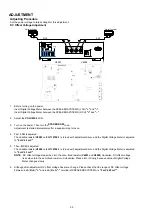

6. STANDBY PCB
Proceeding : TOP COVER
→
STANDBY PCB
(1) Remove the connector wires. Remove the screws.
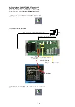
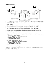
7. TRANS POWER
Proceeding : TOP COVER
→
TRANS POWER
(1)
Cut the wire clamper and remove the connector wires. Remove the screws.
N8501
N8507
N8503
N8505
N8502
STYLE
PIN
PCB HOLDER
N8504
N8001
N8504
N8301
N8505
CUT
STYLE
PIN
17
Содержание Icemaker
Страница 8: ...Personal notes 8...
Страница 27: ...10 Click the E P R 11 Click the OK 27...
Страница 29: ...14 Click the Exit 15 Remove the AC plug for power off this unit 16 Remove the SPK 581 form this unit 29...
Страница 39: ...Personal notes 39...
Страница 43: ...WIRING DIAGRAM 43...
Страница 65: ...TC7WHU04FU DIGITAL U301 U303 U804 U805 65...
Страница 66: ...PCM9211 DIGITAL U302 PCM9211 Block Diagram 66...
Страница 67: ...PCM9211 Pin Discriptions 67...
Страница 71: ...CS2000 CP DIGITAL U801 CS2000 CP DIGITAL U3914 Block Diagram 71...
Страница 72: ...TC74LCX157FT DIGITAL U307 U308 72...