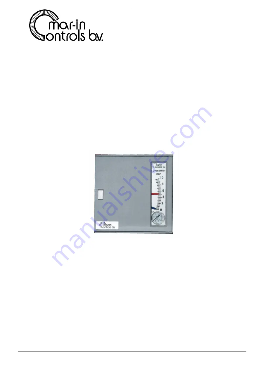
background image


PNEUMATIC CONTROLLER 


 SERIES 

SG6100


Page: 1


MAR-IN CONTROLS B.V.    VAN UTRECHTWEG 8 –10    KRIMPEN A/D IJSSEL    THE NETHERLANDS 

Tel. + 31 (0)180 - 51 71 51 Fax +31 (0)180 - 51 89 14  [email protected]   www.mar-in-controls.com


 TECHNICAL 

MANUAL 

 
 CONTROLLER 


Pneumatic controller SG 6100


Содержание SG 6100

Страница 1: ...00 Page 1 MAR IN CONTROLS B V VAN UTRECHTWEG 8 10 KRIMPEN A D IJSSEL THE NETHERLANDS Tel 31 0 180 51 71 51 Fax 31 0 180 51 89 14 info mar in controls com www mar in controls com TECHNICAL MANUAL CONTROLLER Pneumatic controller SG 6100 ...

Страница 2: ...s 192 x 192 mm DIN 43700 protection grade IP 55 IEC 144 material Reinforced Technopolymer Control Unit Motion balance Control actions and ranges of adjustment P BP 2 200 Kp 50 0 5 P I BP 4 400 Kp 25 0 25 Ti 0 1 25 min Direct Reverse acting reversible by rotating the BP dial Intrinsic Proportional Band P I 0 5 Drift for variation of ambient temperature within 20 and 60o C 0 035 C Drift for variatio...

Страница 3: ...n controls com www mar in controls com Pressure Vacuum Receiver AISI 316 C type tube spring connection 1 4 NPT f overpressure 25 u s v Temperature mercury filled AISI 316 st st bulb with connection 1 2 NPT m Adjustable immersion 350 mm AISI 316 st st capillary 3m length Over temperature see codification Mounting panel or wall Options protection IP 65 capillary 6 m length ...

Страница 4: ... 100 linear B 0 2 1 bar 0 10 square root C Temperature Overrange Y 20 40o C 70 160 H 0 60o C 70 160 K 0 100o C 140 105 L 0 160o C 240 75 M 0 250o C 320 75 N Options without 0 capillary 6 m 1 feature as per IP 65 2 feature as per IP 65 with 6 m of capillary 3 mounting bracket for 2 inch horizontal or vertical pipe 4 Ambient temperature 40 to 70 C Material case Reinforced technopolymer Protection gr...

Страница 5: ...180 51 71 51 Fax 31 0 180 51 89 14 info mar in controls com www mar in controls com Installation Mounting The mounting bracket see fig 1 is suitable for either wall or panel mounting On request the controller can be furnished with Bracket for a 2 horizontal or vertical pipe Tie rods for mounting on control valve Fig 1 Mounting ...

Страница 6: ...auge Before connecting the controller purge the supply line Connection of measuring element to the process Temperature Install the bulb as shown in figure Assure full immersion in the process of the sensing part of the bulb Do not overrange the instrument Do not use a naked flame to heat the bulb When thermowells are used we suggest to apply a thermal heat transfer media liquid or metal powder acc...

Страница 7: ...ours into the instrument When the instrument is mounted above the pressure connection the height of the vertical leg to the instrument should not exceed 7 5 metres divided by the specific gravity of liquid in the leg Steam pressure measurement Pressure connection should be made one top of the vessel or pipeline when the instrument is mounted above or to the side When the instrument is mounted belo...

Страница 8: ...lean copper pipes o d 6 mm i d 4 mm Mount the instrument with a block needle valve It is important that the connection between the instrument and transmitter is leak free To check for leaks apply a solution of soap water onto the connections Before connecting the instrument purge the airline to remove moisture and solids Description of operation fig 4 5 Series SG 6100 controllers are motion balanc...

Страница 9: ... Measuring element link 14 Differential movement 16 Control unit link 17 Output gauge 18 Control unit Proportional Proportional plus Integral action 19 Pneumatic amplifier relay 20 Calibrated orifice 21 Follow up bellows 23 Action lever 24 Proportional spring 25 Manual reset or Adjustment of the pre load of Proportional spring 26 Proportional lever 27 Reset bellows Integral 28 Baffle 29 Nozzle Adj...

Страница 10: ...portional spring until the pointers are coincident e If the variations obtained by b are not persistent oscillations halve the BP value fixed before and repeat a until persistent oscillations are obtained Make hence the operations c and d Controllers with Proportional and Integral Action a Close the Integral Action valve fully to maximum time b Adjust the proportional band in the manner described ...

Страница 11: ...there are any trouble with this relay we recommend to replace it by a new one Switch off the air supply to the instruments Unscrew the screw 19 3 and 19 4 Remove the relay from the instrument Unscrew the top cap 19 1 Unscrew the 4 screws C D E F Remove the top plate and the gasket for replacement gasket specify code PR 7 3 Remove the metal diaphragm with vent baffle in its seat along with the rela...

Страница 12: ...nance Alignment of the Controller The purpose of the controller alignment is to ensure that with the Set Pointer and Measured Value Pointer coincident the Proportional Band Dial may be rotated from Maximum to Minimum without a significant change in the controller output The controllers are usually aligned so that the Set Pointer and Measured Value Pointer coincide and with the Proportional Band se...

Страница 13: ...d Dial to 20 Reverse Action and adjust the minimum Proportional Band adjustment screw 4 to obtain 0 6 0 01 bar Put the Proportional Band to maximum or infinity Reveres Action and turn the maximum Proportional Band alignment screw 5 until the output pressure is 0 6 0 04 bar Repeat the preceding two operations until turning the Proportional Band Dial the output remains 0 6 0 01 bar Put the Proportio...

Страница 14: ...wrong action Leak around Integral restrictor stem Dirty relay stem Proportional Band too wide Reset time too long Friction in the relay valve Friction in the controller proportional lever Proportional Band too narrow Reset time too short Output relay defective Nozzle partially blocked Output air screen plugged Calibrated orifice in the output relay dirty Measuring element link connected to wrong p...

Страница 15: ...on Code 10 Setpoint index 11 Measured value pointer 22 45 12 Measuring element Characteristics indicated on data plate 13 Measuring element link 41 2 92 14 Movement 26 2 34 16 Control unit link 41 61 18 PI control unit PR 8 45 19 Pneumatic relay RE21 RE 21 20 Calibrated orifice F 43 39127 31 Relay base 6 10 Gaskets for RE21 relay PR 7 3 32 Case 33 Dial State graduation 34 Cover PR 8 41 35 Cover ga...

Страница 16: ...7 Integral action restrictor F 47 55034 15 Reaction unit support 21 Follow up bellows PR 8 5 22 Body Body gasket 21 22 23 Reaction lever 26 Proportional motion lever 23 14 27 Integral action reset bellows PR 8 4 28 29 Rotating nozzle baffle assembly PR 8 18 4 x 1 mm silicon rubber tubing 1 5 m Assortment of O rings PR 8 42 Assortment of screws PR 8 43 indicate the recommended spare parts Fig 12 PI...

Отзывы: