Maple Systems OIT3200 Скачать руководство пользователя страница 4

4

OIT3200/3250

1010-0081A, REV 04

Introduction

Thank you for purchasing a Maple Systems OIT3200 or OIT3250. You have

selected a rugged, reliable, and powerful operator interface for your application.

This booklet describes the steps necessary to ensure trouble-free OIT system

operation.

Please read this booklet carefully!!

Static Awareness

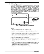
It is best NOT to remove the rear cover on the OIT except when replacing the

real-time clock battery on the OIT3250 (please refer to the “Battery Replacement”

section for more information). When the rear cover is removed, the circuitry inside

is exposed to possible damage by electrostatic discharge during handling.

Minimize the possibility of electrostatic discharge by:
• Discharging personal static by grounding yourself prior to handling the OIT.
• Handling the OIT at static-free, grounded work stations.
• Connecting the chassis of the OIT to a clean ground.
• Placing the OIT into an anti-static bag during transport.

Unpacking the Unit

Carefully unpack the OIT. Please read any instructions or cautions that appear on

the shipping container. Check all material in the container against the enclosed

packing list. Maple Systems, Inc., will not accept responsibility for shortages

against the packing list unless notified within 30 days. The equipment and its

accessories were inspected and tested by Maple Systems before shipment; all of the

equipment should be in good working order. Examine the equipment carefully; if

any shipping damage is evident, notify the carrier immediately. You are

responsible for claim negotiations with the carrier. Save the shipping container and

packing material in case the equipment needs to be stored, returned to Maple

Systems, or transported for any reason.

CAUTION

Содержание OIT3200

Страница 1: ...LARM DOWN MESSAGE PAGE UP NEXT LAST MESSAGE TOGGLE HELP SETUP DELETE CLEAR E N T E R F1 F5 F9 F2 F6 F10 F3 F7 F11 F4 F8 F12 2 3 4 6 5 7 8 MESSAGE ALARM RUN PRINT 1 0 7 4 8 5 1 2 9 6 3 PAGE ACK ALARM D...

Страница 2: ...icense is granted by implication or otherwise under any patent or patent rights of Maple Systems Inc Maple Systems retains the right to revise or change its products and documentation at any time with...

Страница 3: ...0 When power is first applied the OIT s display will indicate that it needs to be configured Use the OITware 200 or STEPware 100 software to create a file or project that can be downloaded to the OIT...

Страница 4: ...to handling the OIT Handling the OIT at static free grounded work stations Connecting the chassis of the OIT to a clean ground Placing the OIT into an anti static bag during transport Unpacking the U...

Страница 5: ...t OIT to Power 11 2 6 Connect OIT to PLC Host 12 3 OIT Configuration Wiring 13 3 1 Connect OIT3200 to PC for Configuration 13 3 2 Connect OIT3250 to PC for Configuration 14 4 OIT3250 Special Features...

Страница 6: ...d from the hinged control panel to the rest of the enclosure 1 2 Power Supply Selection The power supply used to power the OIT should have an output between 12 and 30 VDC The voltage should measure be...

Страница 7: ...inches 20 cm of separation between the OIT cables and other power wiring If voltages greater than 120 VAC are used in the system greater separation is required If theOIT cables must come near ACwiring...

Страница 8: ...wer two pins of a 3 pin header This is called Position A 3 Move the jumper to the upper two pins of the 3 pin header Position B Ensure that the jumper is pressed fully into place 4 Replace the rear co...

Страница 9: ...o Panel INSTALLATION MANUAL 9 1010 0081A REV 04 This area to be free of paint 5 15 0 01 130 8mm 0 3 Corner drill permissable 4 70 0 03 6 00 0 01 152 4mm 0 3 8 00 0 03 1 00 ref 25 4mm 0 23 ref on REAR...

Страница 10: ...Panel The green ground wire assembly supplied with the OIT must be installed as shown This provides a good earth ground connection to the OIT s bezel and rear cover If your control panel is metal be s...

Страница 11: ...to the OIT power supply 3 The power cable should not be any longer than necessary If needed a cut the power supply cable to the appropriate length b strip the cable shield back on the power cable c s...

Страница 12: ...ide or the STEP1 Protocol Operation Manual forinformation onconstructing OIT to ASCII host communication cables STEPS 1 Connect the DE9P plug end of the communication cable to Port 1 on the OIT which...

Страница 13: ...OIT to the computer using an RS 232 serial communications cable P N 7431 0049 purchased separately from Maple Systems The configuration cable should be connected to the proper COM port on your comput...

Страница 14: ...the serial port farthest away from the power connector on the OIT3250 See Figure 10 below for Port 2 pin assignments NOTE Be particularly careful during wiring that Pins 8 and 9 on Port 2 are left ope...

Страница 15: ...hen the OIT is configured Consult the OITware 200 manual for more information Connection to the printer varies depending upon the pinout of the printer See Figure 11 for the OIT Port 2 pin assignments...

Страница 16: ...rnal Alarm Keypress Buzzers Outputs provided on Port 2 of the OIT3250 allow connections for external keypress and alarm buzzers The alarm buzzer output Pin 8 can be used to turn on an external buzzer...

Страница 17: ...e is exposed to possible damage byelectrostatic discharge Refer toStatic Awareness onpage 4 2 Find the coin cell on the PCB It looks like a 1 2 inch 12 7 mm silver disk 3 Insert a small screwdriver in...

Страница 18: ...e made on any non glossy stock between 0 004 inches 0 1 mm and 0 008 inches 0 2 mm thick by either of the following methods Photocopy the blank legends and hand illustrate Use the dimensions to create...

Страница 19: ...81A REV 04 Middle Left 1 3 Right 2 Check Dimension 4 00 101 6 mm Tick marks indicate edge of viewable area F4 F8 F3 F2 F1 F7 F6 F5 F12 F11 F10 F9 Reads this way Function Keys and Logo Product ID Figur...

Страница 20: ...on glossy stock which is 0 004 0 008 inches 0 1 0 2 mm thick Check printing accuracy with a printed check dimension 20 OIT3200 3250 1010 0081A REV 04 1 12 F8 Middle 0 50 Left 0 10 2 5 1 F4 3 F12 Right...

Страница 21: ...refer to Figure 18 6 Carefully remove the factory installed legends 7 Slide in the new legends be gentle avoid wrinkling which makes it hard to push the legend in if the legend moves around too much p...

Страница 22: ...t Liquid Crystal Display LCD 5 x 7 dot matrix with cursor Display Character Size 2 lines by 40 characters 0 2 inches 5 mm high Display Viewing Angle Approximately 120 degrees LEDs 24 for keypress and...

Страница 23: ...F3 F7 F1 F5 Alarm Message 1 Next Message Down Page Page Up Help 7 Setup 4 Ack Last Print Screen 2 3 N 9 Toggle 0 8 R E T 6 5 E Delete Clear 152 4 6 00 9 25 234 9 49 5 1 95 9 7 0 38 2 45 62 1 3 33 4 8...

Страница 24: ...K RED WIRE LIST Pin Shield 30 1 50 0 5 BLK SHIELD 3 RED 2 1 Power Connector 3 1 2 Signal Chassis Ground Signal Ground 12V to 30VDC OIT Push stripped wire into ROUND holes while holding clamps open wit...

Отзывы: