Manzano Laser Works deHavilland DHC-1 Chipmunk Скачать руководство пользователя страница 12

1.

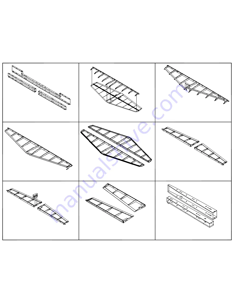
Begin with the stab and elevators. Assembly begins by 

laminating the spars. They are made up from a lamination of 1/8" 

balsa and a lamination of 1/16" plywood. 

Dry fit the stab ribs to the stab spar. Make sure the tabs on the 

spar tips face down.The plywood laminations faces the r bs. 

Place the assembly over the plan. 

With the stab assembly lined up over the plan, dry fit the leading 

edges to the r bs. They will lie flat on the rib tabs. The nose of 

each rib fits in the leading edge notches. When everything is 

properly aligned apply glue to all joints. Also glue the 1/8" balsa 

joined to the center joint of the leading edge pieces. 

2.

3.

4.

5.

6.

7.

8.

9.

Remove the stab assembly from the plan. The r b and spar tabs 

can be removed at this time. The 1/16" balsa center section 

sheeting will be installed during the final assembly steps.

Glue the stab tips to the assembly. The leading edge, tips, and the 

back side of the spar can now be sanded to shape. Refer to the 

plan cross section drawings for the shape of the spar back face. 

The elevators are assembled using the same procedure as the 

stab. Dry fit the r bs to the spars and then place on the plan. The 

plywood side of the spars face the ribs. Add the trailing edge 

pieces so the rear of each rib engages the notches. When 

everything is lined up glue all of the joints.

Plywood boxes made from laminations of 1/32" plywood are used 

to transfer the elevator control horn inputs to the elevator halves. 

Glue the parts for each horn box and then install them in the 

elevator halves. The tabs fit in elevator rib E1.  

Remove the r b and spar tabs. Glue the elevator tips to the 

assemblies. Sand the forward edge of each elevator half to the 

profile shown on the plan cross section drawing. Sand the trailing 

edge to a taper following the the rib top and bottom profile. Also 

sand the elevator tips. 

The fin and rudder assembly is very similar to the stab and 

elevator halves. Begin by making up the fin and rudder spars. 

They are laminated from 1/8" balsa  and 1/16" plywood.

Содержание deHavilland DHC-1 Chipmunk

Страница 1: ...deHavilland DHC 1 Chipmunk Assembly Guide Manzano Laser Works ...

Страница 2: ...s follows Sheet 1 Fuselage Sheet 2 Wing Stab Fin Rudder Sheet 3 Sheeting and part layouts not included on the other plan sheets Materials used in this model include balsa liteply plywood brass tubing and piano wire A formed plastic canopy is also used Most of the wood and the formed canopy is supplied with the kit The builder supplies 3 16 and 1 8 square balsa strip stock piano wire brass tubing a...

Страница 3: ......

Страница 4: ......

Страница 5: ......

Страница 6: ......

Страница 7: ......

Страница 8: ......

Страница 9: ......

Страница 10: ......

Страница 11: ...TAIL SURFACES ASSEMBLY ...

Страница 12: ...de of the spar can now be sanded to shape Refer to the plan cross section drawings for the shape of the spar back face The elevators are assembled using the same procedure as the stab Dry fit the r bs to the spars and then place on the plan The plywood side of the spars face the ribs Add the trailing edge pieces so the rear of each rib engages the notches When everything is lined up glue all of th...

Страница 13: ... the two halves and the key Sand a bevel on the forward face of the rear half of R7 to match the plan profile Glue the halves together using the balsa key to align and strengthen the joint Sand the forward half of R7 to match the joint angle Install R7 Dry fit the rudder tip parts R1 and R2 When satisfied with the fit glue the joint Place the rudder tip on the assembly R2 should be centered on R3 ...

Страница 14: ...WING ASSEMBLY ...

Страница 15: ...e sure all of the ribs are touching the building surface and the 1 8 square strip A few straight pins can help make sure everything stays in the proper place Apply thin CA to all of the joints Make up four paper tubes that are 1 2 in diameter Allow for a bit of overlap when rolling the tubes Two of the tubes need to be 20 long and the other two 7 long Slide one of the long tubes into the forward s...

Страница 16: ...nd for this step Place the wing panel on the building board over the plan when gluing the top leading edge sheeting in place This will help lock in the tip washout Remove the wing panel from the building surface Cut and fit the bottom leading edge sheeting Glue it in place Check to be sure the tip washout has not been altered before the glue dries Glue the wing bolt reinforcement 1 4 balsa laminat...

Страница 17: ...ofile shown by the plan wing cross sections Build the second wing panel following steps 1 through 18 of this assembly guide section The two wing panels are joined using two 1 8 plywood doublers Use epoxy to join the wing panels Glue the center wing dowel to one wing panel before joining both panels With one wing panel laying flat on the building surface the opposite tip should be 6 above the surfa...

Страница 18: ... trays using four wood screws in the corners of the trays 28 29 Bend the landing gear legs using 1 8 diamater piano wire Place the landing gear legs into the slots of the landing gear mounting blocks Place a plywood retaining lug in the pockets of the mount block Mark the location of the retaining screws After all of the screw locations have been marked dirll pilot holes for the screws Run screws ...

Страница 19: ...FUSELAGE ASSEMBLY ...

Страница 20: ...t is flush with the top of the notches in the wing saddle area next to side formers 4 and 7 The parts should be on the wing saddle side of each side former 4S 7S Assemble the two sets of wing saddle parts WS1 through WS3 The wing saddles are then glued to the fuselage internal box and the bottom of the side formers The tabs on the wing saddles fit in the notches of the liteply box sides The bottom...

Страница 21: ...nd part KE The tail wheel leg should rotate freely without any interference from the structure Bend the rudder control horn using 3 32 piano wire Slide a 1 1 8 length of 1 8 brass tubing on the wire after bending the push rod link end and before bending the rudder tiller arm Slide the 1 8 plywood rudder horn support pieces on to the assembly as shown DO NOT APPLY ANY GLUE These parts can slide fre...

Страница 22: ... will be made later Install 3 16 square balsa stringers on the rear fuselage section using the notches in the formers The top stringer will need to be tapered at the rear The taper should start from about 5 1 2 from the rear end of the top stringers The push rod supports are made from two pieces of 1 8 balsa To accommodate the variations in individual builds the supports are trimmed to fit each lo...

Страница 23: ... are four pairs of 1 4 x 1 8 magnets that are used to retain the cowl Install the magnets at this time Glue a magnet in each of the holes in the lower cowl half keel parts Place a magnet on the installed units Mark the outer face of the second set of magnets One at a time remove the second magnet and glue it in the corresponding hole of the upper cowl half The marked face will go toward the inside...

Страница 24: ...FINAL STRUCTURAL ASSEMBLY ...

Страница 25: ...ool used in the previous step Next the stab is installed Before performing that operation connect the elevator control horn to the elevator pushrod clevis Slip one of the balsa stab center section sheeting pieces over the rudder horn Place the stab over the rudder horn on top of the center section sheet Glue the bottom center section sheeting to the stab The tabs on stab ribs S1 align the sheeting...

Страница 26: ...ller laminations together Sand the assembly to match the elevator root rib profile Temporarily fit the elevators to the elevator horn They can be retained with masking tape Glue the elevator filler piece to the fuselage with it centered between the elevators Remove the elevator halves 10 The landing gear leg covers are made from three laminations of 1 8 balsa Glue the center pieces to one side of ...

Отзывы: