DMJOIC201EN - v2
VISIO C2H OPERATOR -
INSTALLATION MANUAL
19
Fig.
7.9
DET
7.9.1
DET
7.9.1
Fig.
7.8
Fig.
7.7
i
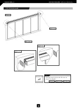
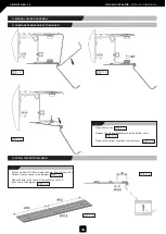
Introduce the 4 trolleys into the main
profile as shown in the diagrams.
Adjust the top wheel in the 4 trolleys
as shown in the diagrams.
Fig.
7.9
DET
7.9.1
Fig.
7.7
Fig.
7.8
i
Attach lock hooks to trolleys 2-3 as
shown in the diagrams.
Fig.
7.5
Fig.
7.6
Fig.
7.6
Tools
Nuts & bolts
DIN7380 6x10
DIN6798 M-6
Fig.
7.5
7.1.3 Lock hooks assembly.
7.2 INTRODUCE TROLLEYS INTO MAIN PROFILE


