background image


12 

D00729EN - v2 

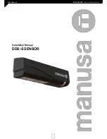
DDS-SSENSOR 

- INSTALLATION MANUAL 

NAVIGATION MAP:

ZIP: All values in compressed format
ID#: Unique identification number 
ERRORS the last 10 errors
AIR: SPOTVIEW View of the spots that trigger detection
AIR: C1 ENERG. Signal  amplitude received from curtain 1
AIR: C2 ENERG. Signal  amplitude received from curtain 2
POWER SUPPLY Connector power supply
OPERATINGTIME Power duration since first startup
RESET LOG Delete all saved errors
RC PASSWORD Password for remote control login
LANGUAGE.  LCD menu language


3 USER MENU 

DIAGNOSTICS

ADMIN Enter code to access the Administrator mode

BASIC MENU

Back
Next
PRESETTINGS

IR: WIDTH

Next

PULSE INPUT. Positive < Negative

FACTORY VALUES <full reset < partial reset

Standard: factory values
Critical Environment: increased immunity 

IR: FREQUENCY. A < B. Detectors installed close together should have different frequencies.
Next

ADVANCED MENU

Back

Back

IR: NUMBER Service mode < 1 < 2 
IR: TPOMAXP. Motion < 15s < 30s < 1min < 2 min < 5 min < 10 min < 20 min < 60 min < infinite

Next
Back

For conformity with EN 16005 / DIN 18650, use values 6 
y 7 at a mounting height ≥ 2,8m. 
BS7036: for a mounting height ≥ 2,2m use values 6 y 7. 
* Values 4 and 5 exclude the door from complying with 
EN 16005 / DIN 18650 / BS 7036 

IR: IMMUNITY.

< 2,8 m 

It is always necessary to adjust the position of the arrows with a screwdriver.


Service mode = Detections deactivated 15 min for maintenance tasks. 
This value excludes compliance of the door systems with EN 16005 and with DIN 18650


IR: OUTPUT. Pulse

DIN 18650 ≥ 1min 
EN 16005 ≥ 30 sec


> 2,8 m 

Partial reset: Outputs do not reset 

(1)

Low<

(2)

Normal<

(3)

High<

(4)

+High*<

(5)

++High*< 

(6)

Normal< 

(7)

High

Содержание DDS-S

Страница 1: ...1 D00729EN v2 DDS SSENSOR INSTALLATION MANUAL Installation Manual DDS S SENSOR ...

Страница 2: ...is manual includes all the necessary information required to install the product Keep this manual in a safe place for future reference 1 DESCRIPTION The AIR DPS Sensor is an electro sensitive device for the detection of individuals specifically designed to provide safety to Manusa sliding doors This sensor complies with all the requirements specified in the Standard EN 16005 4 LCD screen Infrared ...

Страница 3: ...r should only be carried out by manusa Any other use of the device different from its intended purpose shall be excluded from the manufacturer s guarantee This device may only be operated with protective low voltage SELV with safe electrical insulation The installing company shall be responsible for the correct installation of the sensor and the door safety elements The manufacturer shall not be l...

Страница 4: ...gative adjustable Impedance Positive pulse 2K to earth 470R to the of the power source Pulse voltage from 6V to 30V Pulse duration from 4µs to 500µs Work cycle Max 50 Output Pulse polarity negative Level No detection Pulse between the of the power source and 0V Detection the of the power source Topology open collector with 4 7K to 3 3V Maximum sink current 25mA with 1K external resistance towards ...

Страница 5: ... start up and settings 2 1 MOUNTING Max 5cm 2 1 2 SURFACE MOUNTING OPTIONAL 136 mm 2 1 1 STANDARD MOUNTING Slide 1 Clip 2 Unclip 1 Presionar 1 1 1 1 1 2 MOUNT DISMOUNT 1 Remove the protective cover 2 Connect the cable 3 Position the drilling template 4 Drill the holes and remove the template 5 Pass the cable through and install the sensor ...

Страница 6: ...6 D00729EN v2 DDS SSENSOR INSTALLATION MANUAL Cut 1 Screw together 2 Clip 3 Clip 4 Unclip 5 Clip 6 Unclip 7 Clip 8 2 1 4 MOUNTING WITH RAIN PROTECTION OPTIONAL 2 1 3 CEILING MOUNTING OPTIONAL ...

Страница 7: ...connect to 12V VERDE MARRÓN AMARILLO BLANCO ROSA GRIS VIOLET SENSOR 12 30V AC DC 2 2 1 CONNECTION TO VISIO OPERATOR FOR OPENING PROTECTION Brown Green Pink Grey Note Configure the following parameter PULSE INPUT positive Sensor 1 Brown Green Pink Grey DDS S 2 2 1 b Connecting two sensors Note Configure the following parameters Sensor 1 PULSE INPUT positive Sensor 2 PULSE INPUT negative Sensor 2 Br...

Страница 8: ...positive Violet 2 2 4 CONNECTION TO ACTIVA OPERATOR FOR CLOSING PROTECTION Sensor Gris Note Configure the following parameters PULSE INPUT positive 2 2 2 CONNECTION TO VISIO OPERATOR FOR CLOSING PROTECTION Sensor Brown Green Pink Grey DDS S Note Configure the following parameter PULSE INPUT positive DDS S DDS S Brown Green Pink Grey Sensor Brown Green Pink ...

Страница 9: ...ce between the inner curtain of the inside door sensor and the inner curtain of the outside door sensor should always be less than 20cm The distance up to the door leaf depends therefore on the thickness of the door leaf CLOSER FARTHER 2 4 OTHER SETTINGS Set the sensor by LCD or choose one of the presettings 1 STANDARD indoor mounting 2 CRITICAL ENVIRONMENT critical or outside installations 3 SHOP...

Страница 10: ...sensor is ready for use 3 The door performs an opening manoeuvre 3 The door performs an closing manoeuvre 4 OK When the LED switches off the sensor is ready for use 5 2 5 1 QUICK SETUP 2 5 2 ASSISTED SETUP After SETUP check that the installation operates correctly before signing off on the setup process IMPORTANT After DDS S setup do a self learning procedure for door automation Visio ...

Страница 11: ...ve output 2 6 2 FACTORY VALUE vs SAVED VALUE Displayed value Factory value Displayed value Saved value 2 6 3 NAVIGATING THE MENUS 2 6 4 CHANGING VALUES Press to access the menu 1 Enter password if required Not during the first minute after the detector comes ON 2 Scroll through the menu items 4 Select BACK to return to the previous menu or display 5 Select MORE to continue to the next level Basic ...

Страница 12: ...l reset Standard factory values Critical Environment increased immunity IR FREQUENCY A B Detectors installed close together should have different frequencies Next ADVANCED MENU Back Back IR NUMBER Service mode 1 2 IR TPOMAXP Motion 15s 30s 1min 2 min 5 min 10 min 20 min 60 min infinite Next Back For conformity with EN 16005 DIN 18650 use values 6 y 7 at a mounting height 2 8m BS7036 for a mounting...

Страница 13: ...witch the power supply OFF and ON again 2 If the LED comes on again replace the sensor RED Flashes rapidly after assisted setup The sensor sees the door during assisted SETUP 1 Check the angle of the infrared curtains 2 Perform another assisted SETUP Vacate the detection field Turns on sporadically The sensor vibrates 1 Check that the sensor is correctly installed 2 Check the position of the cable...

Страница 14: ...TRICTED TO THE MANUFACTURER It is recommended to clean the optical parts whenever necessary and in any case at least once a year with a slightly damp cloth DO NOT use aggressive cleaning products 5 INSTALLATION CHECKLIST Check that the sensor has been firmly installed to avoid external vibrations Do not cover the sensor There are no moving objects or light sources in the detection field There are ...

Страница 15: ...egulation 2004 108 CE Electromagnetic Compatibility Directive 2006 95 CE Low voltage Equipment Directive 2011 65 CE RoHS2 Directive It has also applied the following harmonised standards and technical specifications EN 16005 UNE EN 12978 AS 5007 DIN 18650 BS 7036 UNE EN ISO 13849 Performance level PL c Authorised representative MANUSA DOOR SYSTEMS Av Vía Augusta 85 87 6th Floor 08174 Sant Cugat de...

Страница 16: ... Barcelona España Tel 34 902 321 400 Fax 34 902 321 450 www manusa com NOTE The characteristics detailed in this document are for information only and do not represent any contractu al obligation The manufacturer reserves the right to make modifications without prior warning Last revision July 2015 42 8445 V1 03 2015 ...

Отзывы: