background image

Mantracourt Electronics Limited

  DCell & DSC MantraCAN User Manual 

10 

Shortcut icons can be created on your desktop and shortcut bar. After installation you may be asked to restart the 
computer. This should be done before proceeding with communications. 

When given the option to install IXXAT CAN drivers ensure these are selected, which is the default. 

Running the Instrument Explorer Software 

Having installed Instrument Explorer you can now run the application, which the rest of this chapter is based 
around. 
From the Windows ‘Start’ button, select 

Programs

, then 

Instrument Explorer

 or click on the shortcut on your 

desktop. 

Instrument Explorer Icon 

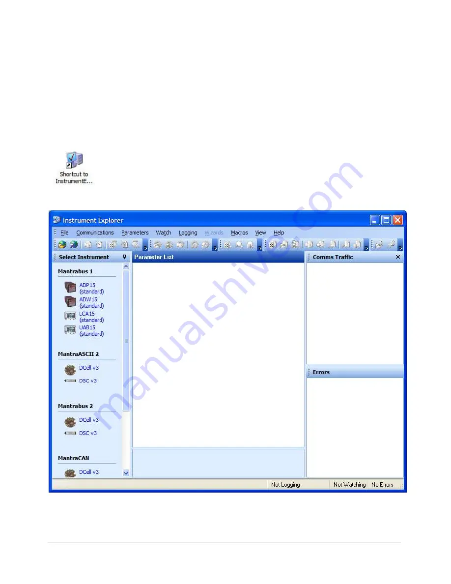
The application should open and look like the following screen shot. Instrument Explorer Window 

The layout of Instrument Explorers Window and child windows allows the user full customisation to their 
requirements. If the application show a different arrangement of child windows than the above screen shot then 
using then load one of the default workspaces as follows: 

Содержание DCell

Страница 1: ...DCell DSC DCell DSC Strain Gauge or Load Cell Embedded Digitiser Module MantraCAN 2nd Generation Software Version 3 onwards User Manual MICRON METERS www micronmeters com metersinfo micronmeters com ...

Страница 2: ...e Data 12 Instrument Explorer Parameter List 12 Connecting a Load Cell 13 DSJ1 Evaluation Board Sensor Connections 14 Performing A System Calibration 15 Chapter 3 Explanation of Category Items 20 Communications 20 ID NODEIDL NODEIDH 20 Example 20 CAN Bit Rate BPS 21 Identifier Size IDSIZE 21 CAN Bus CANTXERR CANRXERR CANSTATUS 21 CANTXERR 21 CANRXERR 22 CANSTATUS 22 Streaming 22 Configuring Output...

Страница 3: ...T 36 Meaning and Operation of Flags 36 Output Update Tracking 36 User Storage 36 USR1 USR9 36 Reset 37 The Reset command RST 37 WARNING Finite Non Volatile Memory Life 37 Chapter 4 The Readings Process 38 Flow diagram 38 Cell System Scaling 39 Calibration Parameters Summary and Defaults 40 Chapter 5 Temperature Compensation 41 Purpose and Method of Temperature Compensation 41 Temperature Module Co...

Страница 4: ...ement 62 Key Requirements 62 Key Requirements 62 Communications Cabling and Grounding Requirements 63 DCell Power and Communications Wiring 63 DCell Bus End Arrangement 63 DSC4 Versions Power and Communications Wiring 63 DSC4 Versions Bus End Arrangement 63 Key Requirements 63 Suitable Cable Types 64 DCell DSC CAN Bus Cable 64 Indication Of Maximum Bus Length 64 CAN Bus Connections for Multiple DC...

Страница 5: ...a component onto custom PCBs High precision Industrial Version 25ppm basic accuracy equates to 16 bit resolution High precision High Stability 5ppm basic accuracy equates to 18 bit resolution with comparable stability far exceeds standard instrument performance Low power Low voltage DC supply 5 6V min typically 40mA for RS485 and 52mA for RS232 including 350R strain gauge Adjustable sensitivity Co...

Страница 6: ...and forces a device reboot as a failsafe to ensure correct operation Version 3 Additions and Enhancements The following are an outline only more detail will be found further on in this manual DCell Easy mounting via a 2mm screw Connection via solder holes to either side of PCB Lower profile dual PCB construction DSC Additional I O Easier shielding connection at load cell connector end DCell DSC Bi...

Страница 7: ...utput Special Aspects To Consider The DCell fits neatly into a strain gauge pocket The DSC lends itself to PCB mounting Additional DCell DSC Variants Available A separate variant is available with RS232 or RS485 output Refer to DCell DSC CAN 2nd Generation Manual These variants are sufficiently different to require their own manuals The following order codes are supported by an earlier version man...

Страница 8: ...e only established during construction so sensors must be replaceable without recalibration Each load monitoring point has a digital load cell fitted with calibration values set during construction Self diagnostics aid detection of failures When a failed load cell is replaced it will produce identical force measurements The old load cell set up data values are programmed into the separate user lev...

Страница 9: ...d have some means of communicating with it The Evaluation Kit Contents An Evaluation PCB DSJ1 which comprises of A 8 way screw connector for the strain gauge Temperature sensor A 5 way screw connector for power CAN comms A 9 way D Type for direct CAN limited to 500Kbps Link headers for CAN RS232 or RS485 comms selection Terminating resistor for CAN RS485 LED for power indication LED for digital ou...

Страница 10: ...supply this should be about 40mA Instrument Explorer Instrument Explorer is Mantracourts own communication interface for our range of standard products It provides communications drivers for the DCell DSC products A complimentary copy is provided on CD ROM with the DCell DSC Evaluation Kit Instrument Explorer can also be downloaded from Mantracourts website http www mantracourt co uk software Inst...

Страница 11: ...d Instrument Explorer you can now run the application which the rest of this chapter is based around From the Windows Start button select Programs then Instrument Explorer or click on the shortcut on your desktop Instrument Explorer Icon The application should open and look like the following screen shot Instrument Explorer Window The layout of Instrument Explorers Window and child windows allows ...

Страница 12: ...he Select Instrument pane of Instrument Explorer Select the relevant device by clicking on the required device icon under the MantraCAN heading Instrument Settings MantraCAN Select the ID The factory default is 1 Select the baud rate to which the device is set The factory default is 500KB Select the ID type Default is 11Bit standard Now click the OK button The above assumes factory defaults If you...

Страница 13: ...structured hierarchic manner enabling the user to expand or contract categories by clicking the and buttons on the left of the list There are four types of parameters and commands Read write Numeric These parameter values are displayed in the right hand column and can be edited by clicking the value The value can then be changed and pressing the Enter key or moving away from the edited value will ...

Страница 14: ...device As parameters are changed the communications traffic is displayed in the Traffic Pane If any errors occur these will be shown in red in the Error Pane Once an error occurs it will need to be reset before any more communications can take place Reset errors by either right clicking the Error Pane and selecting Reset Errors from the pop up menu or select the Communications menu and click the R...

Страница 15: ...e button on the toolbar or click on the Parameters menu and select the Auto Sync item Note that these options toggle so be sure to leave your selection in the active state From the Parameter List click the next to the System heading to expand this level The Parameter List should look as follows This now exposes more levels that can be expanded as required by clicking the next to the heading name D...

Страница 16: ...nd fixed to within about 0 1 accuracy The device also contains two separate user adjustable calibration parameter groups these are termed Cell and System Cell being used to convert from mV V to a force and System to convert this force to required engineering units We shall being using System for the following exercise where we rescale the output value to read in units of your choice and to calibra...

Страница 17: ... Sys Calibration Table A 10 tonne load cell manufacturer gives the following data mV V output Force 2 19053 10 tonne 0 01573 0 tonne Start the wizard by selecting Sys Calibration Table from the Wizard menu Click the Next button and enter the low values as shown below ...

Страница 18: ...has been clamped if the resultant SYS is greater than SMAX or less than SMIN If this is the case then change these values to suitable limits In this example we may set SMIN to 0 5 tonne and SMAX to 12 0 tonne This would then provide clamping of SYS to these values and also a flags being set in FLAG and STAT Sys Calibration Auto Assume we require to calibrate for Kg output and we have available a k...

Страница 19: ...low known test weight and enter the required SYS value for this weight In this case it will be 10 as we want the units of SYS to be Kg Click Next to continue Apply the high known test weight and enter the required SYS value for this weight In this case it will be 100 Click Next to continue ...

Страница 20: ...nt SYS is greater than SMAX or less than SMIN If this is the case then change these values to suitable limits In this example we may set SMIN to 0 5 Kg and SMAX to 110 0 Kg This would then provide clamping of SYS to these values and also a flags being set in FLAG and STAT For detailed information about calibration calculations please refer to chapter 3 ...

Страница 21: ...vice will be on the base ID 1 Because the device ID is set via CAN the device should be the only device connected to the CAN bus while configuring from factory settings Where the DSC parameters are used to define CAN identifiers the following format is used The packet identifier is set using a HI and LO parameter Each of these parameters represents 2 bytes 1 X 16 bit word that are used to create t...

Страница 22: ... Change the device settings in Instrument Explorer by selecting Change Settings from the Communications menu CAN Bit Rate BPS The BPS parameter is a read write byte value specifying a standard communications bit rate according to the following table BPS value 0 1 2 3 4 5 6 7 Bit rate bps 20K 50K 100K 125K 250K 500K 800K 1M Warning When changing this setting it is possible to lose communication wit...

Страница 23: ...acourt protocol Customisable start and stop messages allow the instrument streaming to be controlled via the host CAN network Configuring Output Message Streams The DSC allows up to 4 custom messages to be streamed These are user configurable and can contain data from internal parameters The messages can be streamed at intervals or when the internal parameter value changes or both The highly confi...

Страница 24: ...value sets the number of data bytes contained in the message 0 to 8 MSG1B1 Set the byte value of byte 1 in the message 0 to 255 MSG1B2 Set the byte value of byte 2 in the message 0 to 255 MSG1B3 Set the byte value of byte 3 in the message 0 to 255 MSG1B4 Set the byte value of byte 4 in the message 0 to 255 MSG1B5 Set the byte value of byte 5 in the message 0 to 255 MSG1B6 Set the byte value of byt...

Страница 25: ...l And On Change 2 On Change Only Custom Start Stop When STRMTYPE is set to 2 Custom the streaming is controlled by external packets arriving that match the user defined message defined by the following Start and Stop message matching parameters The identifier and the data can be specified and a matching received message will then start or stop the streaming Although all eight data bytes are availa...

Страница 26: ...B7 The decimal value of data byte 7 that the incoming message must match to start streaming SONB8 The decimal value of data byte 8 that the incoming message must match to start streaming Stop Streaming Parameter Function SOFFIDL The low word value of the message identifier to stop the streaming This will contain the decimal value of the lower word 2 bytes of the ID SOFFIDH The high word value of t...

Страница 27: ...5 MSB 2 Byte 2s Compliment 128 to 127 MSB 3 Byte Sign Bit 127 to 127 MSB The most significant bit indicates a negative number when set to 1 4 Integer Unsigned 0 to 65535 MSB LSB 5 Integer 2s Compliment 32768 to 32767 MSB LSB 6 Integer Sign Bit 32767 to 32767 MSB LSB The most significant bit indicates a negative number when set to 1 7 Long Unsigned 0 to 9999999 MSB LSB 8 Long 2s Compliment 9999999 ...

Страница 28: ...te 1 02 Data Byte 2 00 To configure the DSC to stop streaming on receiving this command STRMTYPE 2 SONIDL 0 SONIDH 0 SONB1 2 SONB2 0 Information Reports the current version of the devices software and the devices unique serial number Note that VERSION is the read able item derived from the devices internal value of VER and SerialNumber is derived from SERL and SERH Software Version VER The VER par...

Страница 29: ...elect the output update rate according to the following table of values RATE value 0 1 2 3 4 5 6 7 8 update rate readings per second 1 2 5 10 20 50 60 100 200 The default rate is 10Hz RATE 3 The other settings give a different speed accuracy trade off Invalid RATE values are treated as if it was set to 3 The underlying analogue to digital conversion rate is 1627Khz These results are block averaged...

Страница 30: ... multiplied by FFST The table below gives an indication of the response to a step input less than FFLV Update Rate is 1 table value of RATE see Chapter 3 Output Rate Control Of Final Value Time To settle 63 Update Rate FFST 1 Update Rate FFST 5 0 1 Update Rate FFST 7 For example If RATE is set to 7 100Hz 0 01s and FFST is set to 30 then the time taken to reach a of step change value is as follows ...

Страница 31: ... can remove the need for the fitting of compensation resistors to the strain gauges This compensation can apply for gain and offset with up to 5 temperature points The input for the temperature compensation is MVV and the output from the process is CMVV If not temperature compensation is invoked the CMVV is equal to MVV Temperature compensation cannot be used at RATE of 8 200Hz A Detailed explanat...

Страница 32: ...nexpected complicating factors relating to installation Method 3 Two Point Calibration Method This is a simple in system calibration procedure and probably the commonest method in practice as in the previous example Two known loads are applied to the system and reading results noted then calibration parameters are set to provide exactly correct readings for these two conditions E G a 10kN 1 tonne ...

Страница 33: ... A command SNAP records the next SYS value and stores in SYSN this is useful where more than 1 device in a system and to prevent measurement skew across the system the SNAP command can be broadcast to all devices ready for polling of their individual SYSN values System Scaling SGAI SOFS The cell output value CELL is scaled with gain and offset using SGAI and SOFS respectively The gain is applied f...

Страница 34: ... in both FLAG and STAT the value of SRAW is also clamped to this value System Zero SZ SZ provides a means of applying a zero to SYS and SOUT This could be used to generate an Net value making SRAW in effect a gross value SYS SRAW SZ Care should be taken on how often SZ is written to see WARNING Finite Non Volatile Memory Life later in this chapter System Outputs SYS SOUT SYS is considered to be th...

Страница 35: ...erent bits of the value represent different diagnostic warnings FLAG is stored in EEPROM and is therefore non volatile STAT is stored in RAM and reset on power up to 0 FLAG is latching requiring reset by the user where as STAT is non latching showing current error status Latched Warning Flags FLAG The flags are normally used as follows FLAG is read at regular intervals by the host like the main ou...

Страница 36: ... 0 ºC Only active when optional Temperature module fitted ECOMUR and ECOMOR are the basic electrical output range warnings These are tripped when the electrical reading goes outside fixed 120 limits This indicates a possible overload of the input circuitry i e the input is too big to measure The tested value ECOM is an un filtered precursor of ELEC CRAWUR and CRAWOR are the cell output range warni...

Страница 37: ...digital input Only available on DSC model Bit set indicates input is closed to 0v V or GND SCALON Used to indicate that the Shunt Calibration command SCON has been issued therefore the shuntcal resistor is now in circuit with the strain gauge bridge SCOF command resets this bit Note that when Shunt Calibration is active the Load Cell Integrity Error will also be generated OLDVAL is set when the de...

Страница 38: ...e all the settings that are retained even when powered down The device EEPROM itself is specified for 100 000 write cycles for any one storage location although typically this is 1 000 000 Therefore When automatic procedures may write to stored control parameters it is important to make sure this does not happen too frequently So you should not for example on a regular basis adjust an offset calib...

Страница 39: ... into the chain of above calculations The named values shown in the boxes are all output parameters which can be read back over the comms link The diagram shows three separate calibration stages called the Electrical Cell and System This allows independent calibrations to be stored for the device itself the load cell and the installed system characteristics Electrical The Electrical calibration pr...

Страница 40: ...e final output value after removing a final user output offset value SZ from SRAW SRAWUR and SRAWOR are output warning limit flags In practice SRAW and SYS can be used to represent something like gross and net values Cell System Scaling Both the Cell and System calibrations are simply linear rescaling calculations i e they apply a gain and offset In both cases four parameters define the scaling of...

Страница 41: ...ilter dynamic level 0 001 FFST Filter Steps max 100 NMMV Nominal 2 5mV V 2 5 RATE Rate 10Hz 3 CGAI basic cell gain 1 0 COFS basic cell offset 0 0 CTN number of temp points 0 CT1 5 temp points Deg C 0 0 0 0 0 0 CTO1 5 offset adjusts 0 0 0 0 0 0 CTG1 5 gain adjusts 1 0 1 0 1 0 1 0 CMIN CRAW min limit 3 0 CMAX CRAW max limit 3 0 CLN number of linearity points 0 CLX1 7 linearity raw value points 0 0 0...

Страница 42: ...n temperature according to a digitally programmed curve These adjustments are automatically applied based on the current device temperature measurement With some care this can remove the need for the usual electrical compensation components altogether Note that the temperature compensation will also remove the temperature drift of the DCell DSC itself if the temperature compensation data is collec...

Страница 43: ...protocol of only being able to enter up to 6 decimal places The CTOx value is subtracted from the uncompensated value CTG1 to CTG5 provide the gain adjustment in ppm terms The actual gain value used is calculated as 1 CTGn x 10 6 Internal Calculation The temperature compensation calculation is described as follows The GAIN correction is applied first The current measured temperature is checked aga...

Страница 44: ...hod 1 Apply a simple linear drift correction i e for known constant gain and offset changes per degree by specifying zero correction at the calibration temperature and appropriately adjusted correction values at extreme temperatures above and below this This can be used when the measurement or sensor has known temperature coefficients Method 2 Where the temperature characteristics of the measureme...

Страница 45: ...r provides a Wizard for the calculation of the parameters required by the DSC DCell This is based on Method 3 where data is collected The wizard allows for small changes in the sampled temperature point that may occur when taking a set of results for gain and offset Also taken into account is any variation in the test weights at different temperatures This is a complex mathematical procedure which...

Страница 46: ...he accuracy requirement is often greater See below for notes of possible difficulties to be avoided Control Parameters Refer to the table in Chapter 9 for command numbers The lookup table based on parameters CLXi CLKi defines an offset adjustment based on the CRAW value which is then added in to give the final CELL output So linearity correction is applied after any temperature compensation The Pa...

Страница 47: ...curacy of the correction If this does happen it shows that the cell calibration is wrong and should be redone The table points must always cover more or less the whole range of output values to be used because corrections are extrapolated outward beyond the first and last points It is always worthwhile including more test points than will be used in the correction table because this gives confiden...

Страница 48: ...4 103 x4 c4 1000 349 97 349 75 220 0 CLK5 103 x5 c5 1000 450 03 449 98 320 0 The CELL output values will now have the required values at all these 5 points Note on the Example If you graph the errors from the above example the results look like this This doesn t show any very definite linear trend so the calibration is okay However there is a big jump between points 3 and 4 which might be worth a ...

Страница 49: ...at the host should actually do with warnings depends on the type and the application Sometimes a complete log is kept sometimes no checking at all is needed Often some warnings can be ignored unless they recur within a short time Warning flags survive power down i e they are backed up in non volatile EEPROM storage Though useful this means that repeatedly cancelling errors which then shortly recur...

Страница 50: ...is used to read back the value of a parameter Response is always sent by the slave on receipt of a valid message The response always returns the command number byte sent by the master A NAK is sent if the Command index is not recognised or if the data sent is invalid Type Descriptor Value Read 1 Write 2 Response 6 NAK 21 Command Number Refer to the table in Chapter 9 for command numbers Data Data ...

Страница 51: ...ged Response From Slave For example if the device did not support command number 10 CAN ID CAN Data Base ID 1 Descriptor Command Number 0x65 0x15 0xA Hexadecimal 101 21 10 Decimal Write To write a parameter send message to appropriate ID with a Write descriptor and IEEE floating point data Message From Master CAN ID CAN Data Base ID Descriptor Command Index Data 11 or 29 bit Write 1 Byte 4 Bytes T...

Страница 52: ...mand To execute command send message to appropriate ID with a Write descriptor and no data Message From Master CAN ID CAN Data Base ID Descriptor Command Index 11 or 29 bit Write 1 Byte Then wait a timeout period for a message of the same ID marked as either Response or NAK descriptor If a response then this acknowledges receipt and does not contain data Successful Response From Slave CAN ID CAN D...

Страница 53: ... converted to or from a floating point representation for reading or writing The rules are as follows For reading integer and byte parameters are treated as unsigned and never read negative i e read value ranges are 0 to 65535 0 and 0 to 255 0 For writing values written to integer and byte parameters are truncated to the nearest integer and negative or positive values are acceptable NOTE Floating ...

Страница 54: ...high RO 32 RATE Reading rate select RW 36 NMVV Nominal mV V for scaling ELEC RW 39 CGAI Cell gain RW 40 COFS Cell offset RW 41 CMIN Cell range min RW 44 CMAX Cell range max RW 45 CLN Number of Linearisation points RW 50 CLX1 7 Linearisation raw values RW 51 57 CLK1 7 Linearisation corrections RW 61 67 SGAI System gain RW 70 SOFS System offset RW 71 SMIN System range min RW 74 SMAX System range max...

Страница 55: ...on to place Data in Packet RW 155 MSG1GAI Gain to apply to data RW 156 MSG1OFS Offset to apply to Data RW 157 MSG1INT Interval to send Data in ms RW 158 MSG1TRG Trigger Type RW 159 MSG2EN Enable message 2 RW 160 MSG2IDL Low word of message 2 CAN ID RW 161 MSG2IDH High Word of Message 2 CAN ID RW 162 MSG2PL Message 1 Packet length 1 8 RW 163 MSG2B1 Byte 1 value RW 164 MSG2B2 Byte 2 value RW 165 MSG...

Страница 56: ... 210 MSG4B8 Byte 8 value RW 211 MSG4SRC CAN command number for required Data RW 212 MSG4FM Data Format RW 213 MSG4SFM Data Sub Format RW 214 MSG4SP Position to place Data in Packet RW 215 MSG4GAI Gain to apply to data RW 216 MSG4OFS Offset to apply to Data RW 217 MSG4INT Interval to send Data in ms RW 218 MSG4TRG Trigger Type RW 219 SONIDL Custom Start ID Low RW 220 SONIDH Custom Start ID High RW ...

Страница 57: ...Mantracourt Electronics Limited DCell DSC MantraCAN User Manual 56 Table Key Denotes a range e g CLK1 7 means CLK1 to CLK7 Access RW RO WO X read write read only write only execute ...

Страница 58: ...d directly to the pads on the top and or bottom of the PCB Care must be taken to electrically insulate the connection pads from the surrounding metal DSC is normally installed in a protective enclosure such as a metal box The pins can be plugged into standard 0 1 pitch PCB header sockets or soldered directly into a host board or to connecting wires It can be mounted either way up Unwanted pins pro...

Страница 59: ...use and have sufficient thermal conductivity to cope with the heat given off up to 1W on a 15V supply DSC no additional electrical shielding is required but moisture and or mechanical protection are often required Any simple box or enclosure can be used If metal the enclosure should be earthed to the SH connection see ...

Страница 60: ...device drops below the 5 6 volts A single device consumes typically 40mA with a 350Ω gauge connected except RS232 output units which use about 10mA more An installation should therefore assume at least 60mA per unit and allow for extra current being taken at power on though supply voltage can safely drop temporarily and for possible voltage drops in long cables Any power supply ripple should be be...

Страница 61: ...tions The Optional Temperature sensor has two connections DQ which provides the bi directional data line and EXC which provides the 0v connection DSC Input Connections Strain Gauge Bridge Connections Are As Follows EXC positive negative excitation supply SIG positive negative output signal SH Shield connection for shield of strain gauge cable GND can be used as the ground connection for the temper...

Страница 62: ...ons V and V are the DC power supply and return connections CANH CANL are the CAN communications connections GND is a communications ground connection SH is the shield ground used for shielding and grounding only OP is the open collector digital output IP is the volt free digital input TS connects to DQ of the optional temperature sensor V V CANH CANL ...

Страница 63: ...ody of the load cell then for optimal performance twin twisted cable should be used although standard 4 core shield cable can be used in low noise environments The M2 mounting hole must be grounded via an M2 screw to the load cell body for specified performance to be met The 2mm mounting hole to accept M2 screw or American equivalent 0 80 Important Note DO NOT USE 2 screw size DSC Strain Gauge Cab...

Страница 64: ...the CAN stays within the required common mode voltage of 2v CANL to 7v CANH The shield should be connected to the earthed enclosure of the power supply DSC4 Versions Power and Communications Wiring The following diagram illustrates how to connect a DSC4 card to the communications and power supply bus cable DSC4 Versions Bus End Arrangement Note The specified cable above shows a yellow wire this wi...

Страница 65: ...he requirements can be specified as follows A suitable type is BICC Brand Rex BE56723 also equivalent to Belden type 8723 In the UK this is available from Farnell part number 118 2117 For bit rates above 500Kbps the following is recommended Belden B3084A Belden B8132 Indication Of Maximum Bus Length The following indication is for the communications lines only It does not include the power lines w...

Страница 66: ...ows a yellow wire this will be replaced with a white wire CALH CALL V V CALH CALL V V CALH CALL V V 120R Terminating Resistor Twisted Pair EMC Gland 360 Terminating 120R Terminating Resistor PSU Twisted Pair CANH CANL CAN GND 120R Terminating Resistor Twisted Pair 120R Terminating Resistor PSU Twisted Pair CANH CANL CAN GND V CH GND CANH CANL V V CH GND CANH CANL V V CH GND CANH CANL V ...

Страница 67: ...y If your strain gauge does not deliver a 2 5mV V full scale output you may want to adjust the sensitivity of the electronics hardware and or the software gain controls If you want to test with an input of more than 2 5mV V you will have to adjust the hardware sensitivity to avoid saturating the input If it is less you can correct in software alone but increasing sensitivity will generally improve...

Страница 68: ...increase sensitivity TC is left in place so that the fitted Rg appears in parallel this gives better temperature stability Its value should then be RG 1 0 025 rqd m V V 0 01 Two effects should be noted 1 The purpose of increasing sensitivity is to reduce reading noise which governs the effective resolution Using software gain alone obviously gives reduced performance 2 The sensitivity should howev...

Страница 69: ...MIN or SMAX have not been exceeded No Communications The majority of problems involve a failure to communicate as there are a number of optional settings that must be set the same at both ends of the link For this reason any communications application should always check command responses and flag a problem when there these responses are not activated Possible problems can be categorised according...

Страница 70: ... turn This deals with all possible problems as long as your hardware can deliver all the supported baud rates Recovering a lost DCell DSC Resetting to default ID Due to the configure ability of the devices CAN settings it is important to note all changes made to these settings or you may lose the ability to communicate with the device In particular if the ID is changed from the default it would be...

Страница 71: ...s divs Resolution 100Hz readings Noise stable over 100s 50 000 Counts divs Signal Filter Dynamic recursive type user programmable Optional Temperature Resolution Temperature Measurement Resolution 0 0625 Deg C Temperature Measurement Accuracy 10 to 85 0 5 Deg C Temperature Measurement Accuracy 55 to 125 2 0 Deg C Temperature update Speed 5 Seconds Electrical Power Supply voltage 5 6 12 18 V dc Pow...

Страница 72: ...0 Counts divs Resolution 100Hz readings Noise stable over 100s 10 000 Counts divs Signal Filter Dynamic recursive type user programmable Optional Temperature Resolution Temperature Measurement Resolution 0 0625 Deg C Temperature Measurement Accuracy 10 to 85 0 5 Deg C Temperature Measurement Accuracy 55 to 125 2 0 Deg C Temperature update Speed 5 Seconds Electrical Power Supply voltage 5 6 12 18 V...

Страница 73: ...aken from pcb centre All dimensions are in mm x y Hole diameter Mounting hole 0 0 8 1 2 0 V 3 2 7 9 1 0 V 5 4 6 6 1 0 CAN L 8 0 1 7 1 0 CAN H 8 2 3 0 1 0 Temp sensor DQ 7 1 5 0 1 0 EXC 7 6 4 9 0 7 SIG 8 9 1 4 0 7 SIG 8 1 4 0 0 7 EXC 6 4 6 3 0 7 CE Approvals European EMC Directive 2004 108 EC BS EN 61326 1 2006 BS EN 61326 2 3 2006 Designed and Manufactured In the UK Code No 517 174 Issue 2 8 14 05...

Отзывы: