M&S Systems | 800.421-1587 | www.mssystems.com
17
XDM
4600
Finishing the Zone Keypads
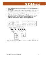
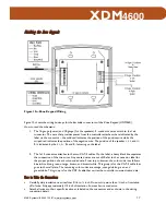
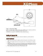
Figure 10—Zone Keypad Wiring
Figure 10 shows the wiring hookups for the backside connectors of the Zone Keypad (XDM46K).
How to read the schematic:
1.
The 16-gauge (power) and 18-gauge (for the speakers), 2-conductor wires attach to the 1x6
connector. The wire that provides power from the controller attaches where indicated by the
label on the connector – the solid red indicates the position of the positive wire while the
striped red indicates the position of the negative wire. The position of the s/- L and +/-
R is indicated by the L+, L-, R+ and R- lettering on the label.
2.
The 1x10 connector attaches to the two CAT-5 cables. On the label, a heavy black line separates
the connection of the two wires. Any unused wires are cut off. Refer to the connector label for
the proper position of each color-coded wire. From top to bottom, the color code is as follows:
blue/white, blue, green, orange, brown, and brown/white. This group is for the CAT-5 cable that
goes to the wall plate. The remaining color codes are orange, orange/white, green, and
green/white. This group is for the CAT-5 cable that carries the controller communication data.
How to Make the Connections
•
Carefully strip insulation on wires from 3/16 to ¼ inch. Do not strip more than ¼ inch of insulation
off of wire. Strip approximately 1/4 inch of insulation from each wire conductor.
•
Attach all wires to their specific location as labeled on the connectors and as shown in the wiring
connection detail.
115951B.pdf 22
115951B.pdf 22
12/16/2005 8:06:47 AM
12/16/2005 8:06:47 AM

