


7
2.4 WORK SEQUENZE
Please note the safety instructions and warnings in point 2.3!
Select suitable clamping jaws for the hose mandrel geometry and insert them (at
(9)). Depending on the clamping jaw design, it is necessary to insert or remove the
clamping jaw adapters (9).
Move the clamping jaws apart while turning the outer hexagon (5) to the left with
the key until the clamping device engages.
Cut both ends of the hose mandrel to be connected flat.
Insert the hose mandrel in the middle of the clamping jaws and hold it with the
clamping lever (6). Tighten the head bolt (10) with the Allen key. Repeat the proce-
dure for the other side.
There should now be a minimal welding gap between the two ends of the hose
mandrel (light gap).
Warning: It is not necessary to tighten the pull studs all the way if the belts are
fixed in the RSX01 welding unit. It is sufficient to clamp them tightly to prevent
the tubular mandrel from slipping out of the jaws. Too much tension can cause
damage to the tension bolts.
STOP
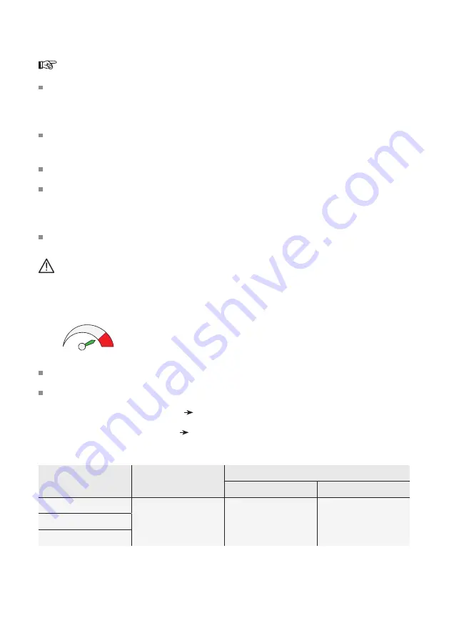
Adjust the speed controller (2) (steps 1 - 6) depending on the profile to be welded.
Adjust the welding pressure on the setting knob (8).
Strongly pressed in position full welding pressure
Slightly depressed position half welding pressure
Material
Speed
Welding pressure
Ø <10 mm
Ø >10 mm
PP
3 ±1
full
welding pressure
half
welding pressure
Nylon (PA)
TPEE