background image

FDMQ 120 - Fire damper

Page 4

Version 2022-12-20

TPM 166/22

Design

Design with mechanical control

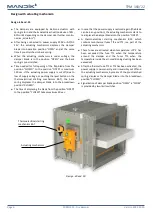
Design .01 with mechanical control can be complemented
with a limit switch signalling of the damper blade position
"CLOSED".

Cable is connected directly to limit switch.

Limit switch detail 

→ see page 5

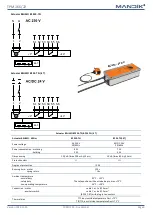
Design .11

Design .01 with mechanical control can be complemented
with  a  terminal  switches  signaling  of  the  damper  blade
position "CLOSED" and "OPEN".

Limit  switches  are  connected  via  damper  casing,  cables
are connected directly to limit switches.

Limit switch detail 

→ see page 5

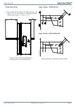
Design .80

Design with mechanical control with a thermal protective
fuse which actuates the shutting device, after the nominal
start temperature 72°C has been reached.

Automatic initiation of the shutting device is not activated
if the temperature does not exceed 70°C.

In  case  that  other  start  temperatures  are  required,
thermal fuses with nominal start tempe104°C or
+147°C  can  be  supplied  (this  requirement  must  be
specified in the order).

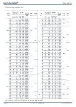
Design .01

ATTENTION:

Mechanisms are produced in five designs M1 to M5, dif-
ference is only in size of inner spring, which closes the fire
damper.

For the size of fire dampers is always assigned the size of
mechanism 

→ see pages 14 to 19

It is not recommended to use different size of mechanism,
than given by the manufacturer, otherwise, there is a risk
of fire damper destruction.

Design .01

Design .11

Limit switch

“CLOSED”

Design .80

Limit switch

“CLOSED”

Limit switch

“OPEN”

Содержание FDMQ 120

Страница 1: ...dik mandik cz Manufacturer MANDIK UK Ltd 130 Aztec West Bristol BS32 4UB United Kingdom Tel 44 117 4526376 E Mail help mandik co uk Authorized representative FDMQ 120 Fire damper Technical Documentati...

Страница 2: ...ement of installations 22 Installation in solid wall construction 23 Installation outside solid wall construction 27 Installation in gypsum wall construction 29 Installation outside gypsum wall constr...

Страница 3: ...ing mechanism back spring Closing spring is released either by pushing of the button or by thermal fuse The back spring of the actuating mechanism is started when the thermoelectrical starting mechani...

Страница 4: ...se which actuates the shutting device after the nominal start temperature 72 C has been reached Automatic initiation of the shutting device is not activated if the temperature does not exceed 70 C In...

Страница 5: ...protection IP 67 Working temperature 25 C 120 C Limit switch G905 300E03W1 This limit switchis possibleto connect infollowing two versions CUT OFF if the arm is moving connect wire 1 2 SWITCH ON if t...

Страница 6: ...he damper blade into the breakdown position CLOSED The time of displacing the blade from the position OPEN to the position CLOSED takes maximum 20 sec In case that the power supply is restored again t...

Страница 7: ...Imax 8 3 A 5 ms Protection class II III Degree of protection IP 54 Running time motor spring return 60 s 20 s Ambient temperature normal duty safety duty non operating temperature 30 C 55 C The safe p...

Страница 8: ...class II III Degree of protection IP 54 Running time motor spring return 60 s 20 s Ambient temperature normal duty safety duty non operating temperature 30 C 55 C The safe position will be attained u...

Страница 9: ...Degree of protection IP 54 Running time motor spring return 120 s 16 s Ambient temperature normal duty safety duty non operating temperature 30 C 50 C The safe position will be attained up to max 75...

Страница 10: ...rting mechanism BAT If the thermal fuse Tf1 breaks for a temperature close to the fire damper it is necessary to replace the actuating mechanism Thermoelectric starting mechanism BAT is integral part...

Страница 11: ...quired with MANDIK control systems OVERRIDE MDCM 6 5 4 3 2 1 L N N L MOTOR POWER COMMS S S F1 S5 S6 S4 S3 S2 S1 COMMS OPEN CLOSED COMMAND L L N L S90C CONTROLLER S90 mounted in an addressablesmoke con...

Страница 12: ...casing 2 Actuating mechanism 3 Damper blade 4 Inspection hole covering 5 BAT thermoelectrical starting mechanism 6 Hole for camera FDMQ 120 with mechanical control 1 Damper casing 2 Mechanics 3 Damper...

Страница 13: ...body by the value c or a These values are specified in chapter Technical parameters see pages 14 to 19 Values a and c has to be respected when projecting related air conditioning ducts Flange of Dampe...

Страница 14: ...1170 300 73 11 5 13 0 0364 700 28 273 21 22 5 0 1270 315 80 5 12 13 5 0 0388 710 33 278 21 22 5 0 1290 355 100 5 13 14 5 0 0450 750 53 298 22 23 5 0 1370 400 123 14 15 5 0 0519 800 78 323 23 24 5 0 14...

Страница 15: ...30 5 0 2261 M3 355 100 5 15 5 17 5 0 0798 800 78 323 29 32 0 2426 BF 400 123 17 18 5 0 0921 400 x 150 12 6 12 7 0 0319 BFL M1 450 148 18 21 0 1059 180 13 13 5 15 5 0 0431 500 173 19 5 22 5 0 1196 M2 2...

Страница 16: ...123 22 23 5 0 1591 M2 600 x 150 16 1 16 2 0 0489 BFL M1 450 148 23 5 26 5 0 1829 BFN 180 13 17 5 19 5 0 0661 500 173 25 5 28 5 0 2066 200 23 18 20 5 0 0776 550 198 27 30 0 2304 BFN 225 36 18 5 21 5 0...

Страница 17: ...23 5 0 0979 550 198 34 35 5 0 3031 225 36 22 5 24 5 0 1160 560 203 34 5 37 5 0 3094 BF 250 48 23 25 5 0 1341 600 223 36 39 0 3344 280 63 24 27 0 1559 M2 630 238 37 40 0 3531 300 73 24 5 27 5 0 1704 6...

Страница 18: ...0 4944 355 100 5 42 5 45 5 0 3553 650 3 248 44 5 47 5 0 5119 400 123 45 5 48 5 0 4104 700 28 273 47 50 0 5556 450 148 49 52 0 4716 BF M3 710 33 278 47 50 0 5644 500 173 47 5 50 5 0 5329 750 53 298 49...

Страница 19: ...kg servo kg 1500 x 180 13 36 37 5 0 1696 BFL M2 1500 x 500 173 57 60 0 6416 BF M3 200 23 37 5 39 0 1991 550 198 58 5 61 5 0 7154 225 36 39 5 41 0 2360 560 203 59 5 62 5 0 7301 250 48 41 5 43 0 2729 BF...

Страница 20: ...otected according to the certified install ation method see pages 23 to 37 During the installation and plastering process the control mechanism must be protected covered against damage and pollution T...

Страница 21: ...ctive covering must be protected with fire fighting insulation If damper is installed outside a construction it is necessary to use reinforcing frame VRM Q 120 see page 48 Examples of fire damper inst...

Страница 22: ...ortar or gypsum 24 25 Ablative Coated Batt 26 Outside solid wall construction ISOVER Ultimate Protect Ablative Coated Batt 27 28 In gypsum wall construction Mortar or gypsum 29 Battery mortar or gypsu...

Страница 23: ...ed minimum density 670 kg m 4 Fixing profile with threaded rod see pages 38 to 40 5 Duct Solid wall construction mortar or gypsum EIS 120 X X 100 50 150 50 150 100 B min B 100 max B 300 A min A 100 ma...

Страница 24: ...sity 66 kg m e g ISOVER Ultimate Protect SLAB 4 th 60 mm Solid wall construction 2 battery mortar or gypsum EIS 120 X Y 50 150 50 150 Y X 100 100 B min B 100 max B 300 2xA 60 min 2xA 60 100 max 2xA 60...

Страница 25: ...e of stone wool min density 66 kg m e g ISOVER Ultimate Protect SLAB 4 th 60 mm 63 12 A B 29 X 100 Solid wall construction 4 battery mortar or gypsum EIS 120 X 50 150 min 2xA 60 100 max 2xA 60 300 2xA...

Страница 26: ...TOP CC or equivalent 5 Duct 6 Protective cladding boards not part of the damper but must be used as part of the penetration filling It can be ordered from MAND K as an accessory e g PROMATECT MST th 3...

Страница 27: ...red separately for each installation case see page 48 Outside solid wall construction ISOVER Ultimate Protect Ablative Coated Batt EIS 120 1 FDMQ 120 2 Solid wall construction 3 Ablative Coated Batt e...

Страница 28: ...7 ISOVER Protect BSK glue apply on the insulation and stick it to the fire separation construction 8 Fire resistant mastic fill the gap on both sides of the fire separation construction and around the...

Страница 29: ...file with threaded rod see pages 38 to 40 5 Duct X X 100 50 150 Installation in gypsum wall construction Gypsum wall construction mortar or gypsum EIS 120 B min B 100 max B 300 A min A 100 max A 300 5...

Страница 30: ...sity 66 kg m e g ISOVER Ultimate Protect SLAB 4 th 60 mm Gypsum wall construction 2 battery mortar or gypsum EIS 120 X Y 50 150 50 150 Y 100 min 2xB 60 100 max 2xB 60 300 2xB 60 A A min A 100 max A 30...

Страница 31: ...e of stone wool min density 66 kg m e g ISOVER Ultimate Protect SLAB 4 th 60 mm 63 12 A B 29 X 100 Gypsum wall construction 4 battery mortar or gypsum EIS 120 X 50 150 A A min 2xA 60 100 max 2xA 60 30...

Страница 32: ...ROMASTOP CC or equivalent 5 Duct 6 Protective cladding boards not part of the damper but must be used as part of the penetration filling It can be ordered from MAND K as an accessory e g PROMATECT MST...

Страница 33: ...ind of installation always VRM Q 120 is not a part of the Fire damper and must be ordered separately for each installation case see page 48 1 FDMQ 120 2 Gypsum wall construction 3 Ablative Coated Batt...

Страница 34: ...otect BSK glue apply on the insulation and stick it to the fire separation construction 8 Fire resistant mastic fill the gap on both sides of the fire separation construction and around the perimeter...

Страница 35: ...with threaded rod see pages 38 to 40 5 Duct Installation in solid ceiling construction Solid ceiling construction mortar or gypsum EIS 120 X X 150 70 150 70 150 150 A A A min A 140 max A 300 A B min B...

Страница 36: ...h Gy proc CoreBoard between studs secured by Gypframe Retaining Channel 25mm Isover Acoustic Partition Roll APR 1200 in cavity optional Lining boards to non shaft side see table below Studs at 600mm c...

Страница 37: ...wall British gypsum mortar or gypsum EIS 120 For connection following duct see page 40 Follow the instructions of the shaft wall producer All technical specifications and conditions can be found at w...

Страница 38: ...6 157 96 192 M18 192 117 234 M20 245 150 300 Without anchor With anchor Possible examples of anchoring to the ceiling construction Follow the instructions of fixing specialist or installation company...

Страница 39: ...0 2 Threaded rod M8 M20 3 Support HILTI MQ 41 or MQ 41 3 or equivalent 4 Bored plate HILTI MQZ L or equivalent 5 Washer for M8 M20 6 Nut M8 M20 max 50 Dimension elements of the suspension system acc t...

Страница 40: ...FDMQ 120 Fire damper Page 40 Version 2022 12 20 TPM 166 22 Duct connection 1 FDMQ 120 2 Connecting air duct 3 Extension piece if required 4 Damping pad or breakaway connection as DW 144...

Страница 41: ...DATA Pressure loss Pressure loss calculation Determination of pressure loss by using diagram 1 2 kg m3 p w2 2 p Pa presure loss w m s air flow speed in nominal damper section kg m3 air density coeffi...

Страница 42: ...9 0 219 750 0 354 0 330 0 321 0 309 0 286 0 271 0 260 0 246 0 238 0 230 0 222 0 219 0 215 800 0 344 0 320 0 309 0 297 0 282 0 264 0 251 0 239 0 229 0 221 0 215 0 211 0 209 A B 600 630 650 700 710 750...

Страница 43: ...44 1 47 3 49 5 51 3 52 7 53 9 54 9 55 8 56 6 59 8 62 63 8 65 2 67 4 69 2 72 8 74 5 7 48 2 51 3 53 5 55 3 56 7 57 9 58 9 59 8 60 7 63 8 66 1 67 8 69 2 71 4 73 2 76 8 78 6 8 51 6 54 8 57 58 8 60 2 61 4...

Страница 44: ...lder 1 lock lever 2 lock spring 8 dia stopper pin mechanics pin 5 Inspection hole cover including the clip and fasteners if they are parts of the cover 6 Bearing for torque transfer from the lever wit...

Страница 45: ...LOSED position Dampers are stored indoor in environment without any aggressive vapours gases or dust Indoor temperature must be in the range from 30 C to 50 C and maximum relative humidity 95 avoid co...

Страница 46: ...the required device to the base plate of the damper The said facts must be recorded in the respective operation documentation of the damper record books of the damper fire logs etc and subsequently a...

Страница 47: ...e damper TPM 166 22 1 Damper 6 Fusible link 2 Mounting plate 7 Mechanics 3 Sealing cover 8 Actuator 4 Seal plates 9 Temperature sensor 5 Mounting plate cover 10 Sensor sticker Change of mechanical des...

Страница 48: ...cing frame VRM Q 120 Fixing reinforcing frame VRM Q 120 to the damper casing Installation procedure 1 Apply K84 glue over the entire surface 2 Attach the frame parts to the damper and screw it in the...

Страница 49: ...position Release of the locking mechanism can be achieved manually or automatically by applying the supply voltage It is recommended to provide periodical checks maintenance and service actions on Fir...

Страница 50: ...the function checks the dampers should be moved to CLOSED position with the fan off or with closed regulation valve situated between the fan and the fire damper Before putting the dampers into operat...

Страница 51: ...With actuating mechanism BF 230 TN BFL BFN 230 T voltage AC 230 V 40 With actuating mechanism BF 24 TN BFL BFN 24 T voltage AC DC 24 V 50 design Reinforcing frame VRM Q 120 damper placement outside wa...

Страница 52: ...ual product information see www mandik co uk MAND K a s Dob sk 550 267 24 Hostomice Czech Republic Tel 420 311 706 742 E Mail mandik mandik cz Manufacturer MANDIK UK Ltd 130 Aztec West Bristol BS32 4U...

Отзывы:

Похожие инструкции для FDMQ 120