background image

Tuffnote  10

  User  Guide 


24 

M&A Technology Inc.                        Toll Free: 800-225-1452                                  www.macomp.com 


2.2.3.  Plugging to the DC supply 

The AC adapter provides external power source to your system and charges the internal battery pack at the same 
time. The AC adapter also has an auto-switching design that can connect to any 100VAC ~ 240VAC power outlets. 

To connect the power adapter: 

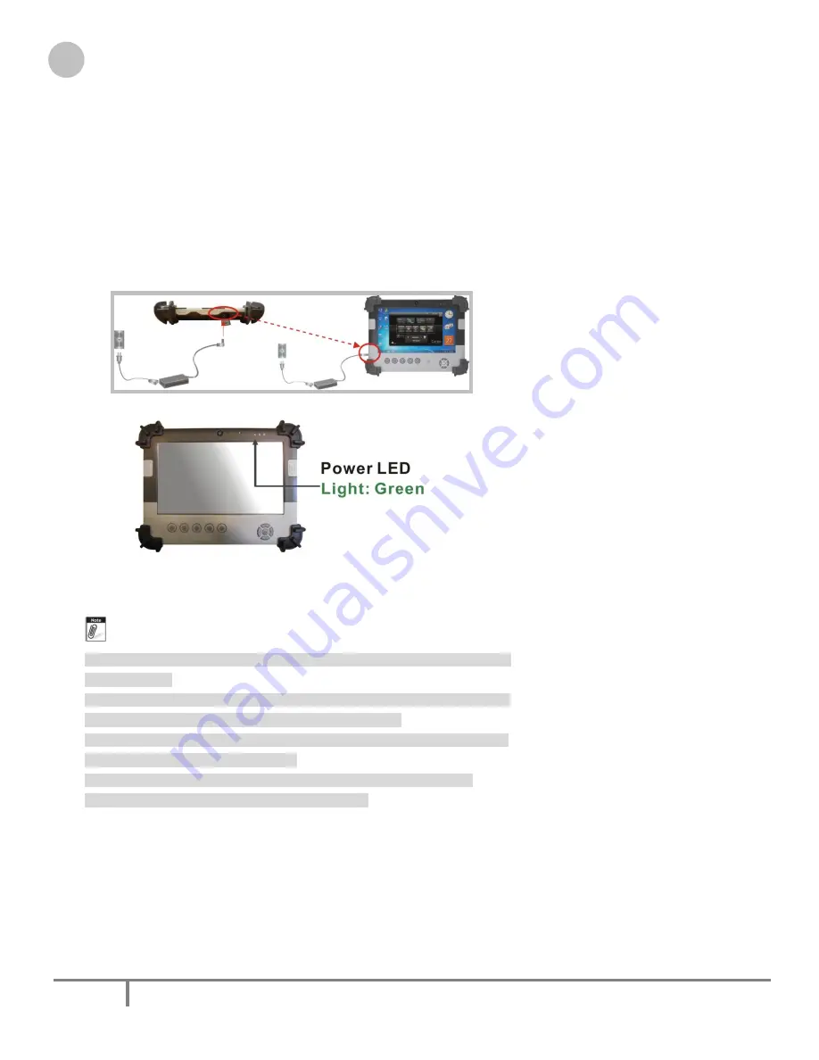
1.  Plug the AC adapter connector to the DC-Jack socket on the left side of the system. 
2.  Plug the power cord to the AC adapter. 


3.  Plug the other end of the power cord to a live wall outlet, at the same time, the Power LED at face panel lights 

up green. 


--    For the power supply of this equipment, an approved power cord has   
 

to be used. 

--    Make sure the socket and any extension cord(s) you use can support   
 

the total current load of all the connected devices.   

--  Remove all power from the device prior to installing or removing any   
 

accessories, hardware, or cables 

--    Before cleaning the system, make sure it is disconnected from   
 

any external power supplies (i.e. AC adapter). 

2.2.4.  Starting Your System 

The Power/Resume button is found on the left side of the Tablet PC. Press the Power/Resume button to start your 
system and check that if the Power LED turns on. 

After a few seconds, the system’s display will turn on and your system will begin to execute the Power On Self Test 
or POST to check if all system components are running properly. Any error found during the test will be displayed 

Содержание Tuffnote 10

Страница 1: ...M M A A T Tu uf ff fn no ot te e 1 10 0 U Us se er r G Gu ui id de e V Ve er rs si io on n 1 1 2 2 ...

Страница 2: ...u cannot get it work according to user manual d The equipment has dropped and damaged If the equipment has obvious sign of breakage 9 Caution on use of battery Use the battery recommended by the manufacturer or the same type of battery installed by the manufacturer If incorrect battery is used it may cause explosion or fire hazard Recycle or discard used batteries according the manufacturer s inst...

Страница 3: ...t and receiver Connect the equipment into an outlet on a circuit different from that to which the receiver is connected Consult the dealer or an experienced radio TV technician for help FCC Caution Any changes or modifications not expressly approved by the party responsible for compliance could void the user s authority to operate this equipment FCC RF Radiation Exposure Statement 1 This Transmitt...

Страница 4: ... device is a 2 4GHz wideband transmission system transceiver intended for use in all EU member states and EFTA countries under the following conditions and or with the following restrictions In Italy the end user should apply for a license at the national spectrum authorities in order to obtain authorization to use the device for setting up outdoor radio links and or for supplying public access to...

Страница 5: ...nment 10 1 2 6 Material 11 1 2 7 Operation OS 11 1 2 8 Certifications 11 1 2 9 Optional Internal Module 11 1 2 10 Optional External Accessories 11 1 2 11 Optional Packing Lists 12 1 3 Packing List 13 1 4 Dimensions 13 Chapter 2 System Setup 16 2 1 Exploring Your Tuffnote 10 16 2 1 1 The front side of the Tuffnote 10 16 2 1 2 The rear side of the Tuffnote 19 2 1 3 The right side of the Tuffnote 20 ...

Страница 6: ...stem 26 3 4 Installing the Battery optional 27 3 5 UsingaSIM Card 28 3 5 1 Inserting a SIM Card 28 3 5 2 Removing a SIM Card 28 3 6 UsingaBarcode ScannerModule optional 29 3 7 UsingaMSRModule optional 30 3 8 UsingaTrackerModule optional 31 3 9 Using the Docking Stand optional 32 3 9 1 The right side of the Docking Stand 33 3 9 2 The rear side of the Docking Stand 33 Chapter 4 The BIOS Setup Progra...

Страница 7: ... the User Interface 41 5 2 2 Hibernate this System 42 5 2 3 System Status Information 42 5 3 Using the Application 44 5 3 1 Brightness Control 44 5 3 2 Volume Control 44 5 3 3 Webcam Launch 45 5 3 4 Monitor Switch 45 Chapter 6 Maintenance 47 6 1 Maintaining the Battery 47 6 2 Maintaining the LCD Display 47 6 3 Cleaning the Tuffnote 10 47 ...

Страница 8: ...eal for an all around system performance Furthermore Tuffnote 10 semi rugged tablet PC is equipped with fanless design 1 1 2 2 S Sp pe ec ci if fi ic ca at ti io on n The Tuffnote 10 semi rugged tablet PC is a flexible multi functional flat tablet PC With following specifications that can be applied in diverse operational environments and implemented in multi faceted applications 1 2 1 Main System...

Страница 9: ...t Bezel TPM 1 x Compatible with TPM1 2 option Communication 1 x Wireless IEEE 802 11 b g n 1 x Bluetooth 2 1 EDR RFID NFC Frequency 13 56MHz 7KHz Reading Range within 40 50mm depending on type of tags HF RFID Reader ISO IEC 14443A B 15693 Mifare 1K 4K Ultralight NFC IP1 Protocol Webcam Front Bezel 1 3 Mega pixel Camera audio input Digital Microphone functions Rear Bezel 2 Mega pixel Camera LED aux...

Страница 10: ... AC to DC 19VDC 3 42A 65W AC 100V 240V 50 60Hz input 19 DC in Battery Internal Battery Internal Smart Lithium Polymer Battery 3800mAh 2S1P 7 4V 1 2 5 Environment Operation Temperature 0 C to 40 C MIL STD 810G Method 501 5 and 502 5 Storage Temperature 20 C to 60 C MIL STD 810G Method 501 5 and 502 5 Humidity 5 90 without condensation MIL STD 810G Method 507 5 Drop 4 ft drop to Plywood MIL STD 810G...

Страница 11: ...pproximate 1 2kg with internal battery 1 2 7 Operation OS WES7 WS7E and WES7 WS7P 1 2 8 Certifications EMI FCC part 15 Class B VCCI V 3 V 4 CE EN55022 EN55024 Safety UL EN60950 CE RF FCC part 15 subpart C SAR FCC SAR OET 65 C 1 2 9 Optional Internal Module 3 5G Protocol HSUPA HSDPA UMTS EDGE Frequency CDMA EVDO 850 900 1800 1900MHz 1 2 10 Optional External Accessories MSR Reference Standards Tripl...

Страница 12: ...ernet 1 x HDMI 1 x VGA 1 x Kensington and 1 x DC Jack support External Battery Kits External Battery Pack Hot swappable Lithium Polymer battery pack doubles duration of mobile operation 4200mAh 2S1P 7 4V External Battery Charger Recharges external battery pack Vehicle Application Accessories Vehicle Mounting Docking 4 x USB2 0 type A 2 x RS232 1 x 10 100Mbps Ethernet 1 x VGA and DC Jack support 75...

Страница 13: ...ode 1 Corner Rubber Screw 4 Corner Rubber 4 Shoulder Strap 1 Hand Strap 1 Stylus 1 Accessories Option QTY Barcode Scanner 1 MSR 1 DeskTop Docking 1 Vehicle Docking 1 Vehicle Bracket 1 Vehicle Power Adapter 1 Battery Charger 1 GPS 1 GPS Tracker 1 Carrying Bag 1 Handle Secures 1 More 1 1 4 4 D Di im me en ns si io on ns s The following sections provide information for the Tuffnote 10 dimensions Dime...

Страница 14: ...Tuffnote 10 User Guide 14 M A Technology Inc Toll Free 800 225 1452 www macomp com ...

Страница 15: ...Tuffnote 10 User Guide 15 M A Technology Inc Toll Free 800 225 1452 www macomp com ...

Страница 16: ...de of the Tuffnote 10 is equipped the I O as described below 1 Camera 1 3 Mega pixel 2 Digital Microphone 3 LED Power Storage Wi Fi 4 Light Sensor 5 Barcode Button 6 Navigation Buttons 7 RFID 8 User Interface Button 9 Program Function Buttons 10 Barcode Button Camera 1 3 Mega pixel The built in camera can be used as a communication device for allowing you to capture images record videos and have v...

Страница 17: ...s off it indicates that the function is disabled Light Sensor This sensor works with brightness control When you set the brightness control to Auto for details please refer 5 3 1 it will automatically detect the light environment and adjust the screen brightness according to the operating environment Barcode Button Right Side When Scanner is scanning the Barcode please press Barcode Button simulta...

Страница 18: ...fnote System This port can only receive data or files from other RFID equipped or equivalent device User Interface Button This button is used to define the User Interface function When you press this button the system will appear the UI screen as illustrated below for executing the applications easily and quickly Programmable Function Buttons If your system does not define this button s function t...

Страница 19: ...fnote is equipped the I O as described below 1 Camera 2 Mega pixel 2 SIM Card Optional Accessories Door 3 External Battery Connector 4 5 Speakers 6 Protective Rubber Camera 2 Mega pixel The built in camera can be used as a communication device for allowing you to capture images record videos and have video chats It is 2 0 M pixels and transmitting instant image through network for conference SIM C...

Страница 20: ...em harm from vibration or shock the system has been designed with installing four protective rubber at the four corner 2 1 3 The right side of the Tuffnote The right side of the Tuffnote is equipped the I O as described below 1 Microphone port 2 Headphone port 3 USB port 4 USB port Microphone port Allows you to connect an external microphone for monophonic sound recording directly into your Tablet...

Страница 21: ...have been touched by random you can press the Lock button to halt the system temporarily the screen will appear Lock message To make the system back to work press the Lock button again to disable the halt function the screen will appear Unlock message Note When you press the lock button please hold for 1 second to activate or close this function Wi Fi Button Press this button to activate or close ...

Страница 22: ... close any function please touch the option to close the execution as shown in the following graphics Close Wi Fi function Close Bluetooth function Close 3G function To activate the function please check the option as shown in the following graphics to make the function enabled Activate 3G function Activate Bluetooth function Activate Wi Fi function ...

Страница 23: ...In ns st ta al ll la at ti io on n Your Tuffnote is designed and pre configured for easy setup and use This section describes the installation steps you should follow to get the system running as quickly as possible 2 2 1 Installing the Rubber Bumpers To protect the housing case of Tuffnote 10 install the rubber bumpers 1 Place the Tuffnote 10 to rear side and install the rubber bumpers to the 4 c...

Страница 24: ...or the power supply of this equipment an approved power cord has to be used Make sure the socket and any extension cord s you use can support the total current load of all the connected devices Remove all power from the device prior to installing or removing any accessories hardware or cables Before cleaning the system make sure it is disconnected from any external power supplies i e AC adapter 2 ...

Страница 25: ...ings for your computer optimal operation After the test has completed your computer will start to search and boot up the operating system from your hard drive 2 2 5 Connecting the keyboard and mouse Before setting up the system please make sure the following items are available Keyboard Mouse for system software installation A keyboard is an input device a mouse is a pointing device Please connect...

Страница 26: ...ilip are seven core members of USB IF to have worked on USB 2 0 standardization USB 2 0 offers data transfer rate up to 480Mbps megabits per second compared to USB 1 1 devices which transfer at speeds of 12Mbps So you could know that USB 2 0 can transfer data between the computer and its peripherals 40 times faster than USB 1 1 However USB 2 0 is fully backward compatible you will be able to use a...

Страница 27: ...r installing the battery pack please follow the steps below 1 Turn off the system 2 Align the hook wall at the rear side then place and screw it fixedly 3 Remove the cover of the external battery connector as marked below and place it on the lower position as marked below 4 Snap the battery pack into the external battery connector and hook into the hook wall securely For removing the external batt...

Страница 28: ... the SIM Card firmly but slowly to the SIM Card slot To insert a SIM card into the slot please pay attention only one correct side can be accepted for the card slot If you cannot insert the card into the slot or you had inserted the card but it is not recognized by the Tablet PC please remove the card and insert it again To prevent the damage made both on card and the slot never forced an entry in...

Страница 29: ... 10 is designed with equipped the optional Barcode Scanner module Before installing the barcode scanner module please switch the DIP 1 2 to ON and DIP 3 4 to OFF as indicated in the following graphics To install the Barcode Scanner Module 1 Make sure the system is turned off 2 Unscrew the compartment cover on top of the system 3 Screw the Barcode MSR transfer board into the mainboard Barcode MSR T...

Страница 30: ...m Barcode Scanner Module 3 3 7 7 U Us si in ng g a a M MS SR R M Mo od du ul le e o op pt ti io on na al l Your Tuffnote 10 is designed with equipped the optional MSR module Before installing the barcode scanner module please switch the DIP 1 2 to OFF and DIP 3 4 to ON as indicated in the following graphics To install the MSR Module 1 Make sure the system is turned off 2 Unscrew the compartment co...

Страница 31: ...ector to the connectors inside the compartment 5 Screw to secure the MSR module onto the system MSR Module 3 3 8 8 U Us si in ng g a a T Tr ra ac ck ke er r M Mo od du ul le e o op pt ti io on na al l Your Tuffnote 10 is designed with equipped the optional Tracker module To install the Tracker Module 1 Make sure the system is turned off 2 Unscrew the compartment cover on top of the system ...

Страница 32: ...acker connector to the connectors inside the compartment 5 Screw to secure the Tracker module onto the system Tracker Module 3 3 9 9 U Us si in ng g t th he e D Do oc ck ki in ng g S St ta an nd d o op pt ti io on na al l Tuffnote 10 provides optional of docking stand for you to dock this system when you are at your home or on your office desk Docking Stand Docking Connector ...

Страница 33: ... the docking stand 3 9 1 The right side of the Docking Stand 1 USB port 2 USB port The Universal Serial Bus USB port allows you to connect USB 2 0 compliant devices for example printers scanners and so on to your Tuffnote 10 3 9 2 The rear side of the Docking Stand The rear side of the docking stand provides the following ports and connectors as described below 1 Locking Device Keyhole ...

Страница 34: ...ectors to transfer data HDMI port Lets you connect to the HDMI peripheral device for digital audio video transmitting VGA port Lets you attach an external monitor or projector for wider display You can run the screen display and the external monitor simultaneously LAN port An 10Base T 100Base TX Ethernet LAN module lets your Tuffnote 10 connects to other computers networks through a local area net...

Страница 35: ...ration you change the system backup battery or the system detects a configuration error and asks you to run the Setup program You must have connected a USB type of keyboard and Use the arrow keys to select and press Enter to run the selected program Function Key Please check the following table for the function description of each direction key Function Key s Function Description Moves cursor left...

Страница 36: ...date Follow the month day and year format System Time To set the time highlight the Time field and then press keys to set the current time Follow the hour minute and second format BIOS Version The system will automatically displays the information of BIOS version EC Version The system will automatically displays the information of EC Embedded Controller firmware version Build Time The system will ...

Страница 37: ...when system booting In this section you may set the configurations for the following items Quick boot UEFI boot Legacy boot and Boot Priority Select Language Lets you select the language displayed in SETUP UTILITY The current BIOS support the languages of English Japanese and French UEFI Boot Lets you activate or close the UEFI boot function by selecting Enabled or Disabled option Legacy Boot Lets...

Страница 38: ...en there is no password setting User Password is This option displays the status of User Password If the password is entered it will display Set information or it will display Cleared information when there is no password setting Set Supervisor Password This field let you set or clear the Supervisor account s password Set User Password This field let you set or clear the User account s password TP...

Страница 39: ...Se et tu up p This page allows you to set the search drive sequence where the system will try to boot up first To select the boot device you can use the up or down arrow key then press to move up the device in the list or press to move down the device in the list To exit from this menu press Esc 4 4 5 5 E Ex xi it t C Co on nt tr ro ol l ...

Страница 40: ...scarding Changes When you select this option it will pop out the following message Discard changes and exit setup Select OK to exit the BIOS SETUP UTILITY without saving any changes Load Setup Defaults When you select this option it will pop out the following message Load optimal defaults Select OK to load the default values for all the setup configurations Save Changes When you select this option...

Страница 41: ...hermore it also provides system information for your reference such as battery status RF setting with its signal strength firmware BIOS EC version information Besides these features you can press the soft button to hibernate this device 5 5 2 2 A Ab bo ou ut t t th he e U Us se er r I In nt te er rf fa ac ce e 5 2 1 Enable or disable the User Interface To display the User Interface please press th...

Страница 42: ...shows you the battery capacity status RF status with its signal strength and system information and provides the control panel for the function setting For battery capacity status The Tuffnote 10 is equipped with one internal battery and one optional battery The battery capacity status shown below advises you that only one internal battery is embedded with the system fully charged and there is no ...

Страница 43: ...ds For RF status The following RF status shows you that the system is equipped with Wi Fi Bluetooth and 3G functions There are optional modules for RFID and GPS If you want to close either of these functions please see section for how to configure The following signal strength shows you that the Wi Fi function is connecting currently the stronger the signal strength the more scale will show on the...

Страница 44: ...des you to adjust brightness volume launch webcam make screen orientation and switch monitor 5 3 1 Brightness Control For brightness adjustment press the Brightness command When you press it the brightness control panel is appeared as follows You can click or to reduce or increase the brightness Also you can slide the scale bar to set the brightness Since the system supports the light sensor if yo...

Страница 45: ...o volume incrementally Also you can slide the scale bar to set the audio volume You can check the Mute to make the system voiceless 5 3 3 Webcam Launch For Webcam Launch press the Webcam command to appear the Webcam utility for your application 5 3 4 Monitor Switch For Monitor switch press the Monitor Switch to pop up the selection bar for choosing the display mode within following four options ...

Страница 46: ...he Tuffnote screen and external display device The resolution on these two display modes are same it is not available to adjust the resolution on the external display mode You can click Extend to display the different contents on the Tuffnote screen and external display device You only can adjust the resolution on the external display device You can click Projector only to display on external proj...

Страница 47: ...isassemble the battery and do not place the battery in water or in a fire Do not subject the battery to strong impact such as a blow from a hammer or stepping on or dropping it Do not puncture or disassemble the battery Do not attempt to open or service the battery Replace only with batteries designed specifically for this product Keep the battery out of reach of children Dispose of used batteries...

Отзывы: