99.45
L28/32H
1613538-7.3
Page 2 (3)
Information from the Alternator supplier
G 50 02 8
Project Information should as a minimum contain the
following documentation:
1.
General description of alternator.
2.
"outline" drawing
Following information is required in order to be able to
work out drawings for base frame and general arran-
gement of GenSet.
Side view and view of driving end with all main
dimensions, i.e. length, width, height, foot position,
foot width, shaft height, etc. as well as all the
dimensions of the alternator's coupling flange, alt.
groove shaft pin.
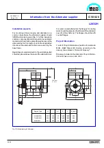
As minimum all the dimensions in fig. 1 should be
stated.
Further the "outline" drawing is to include alternator
type, total weight with placement of center of gravity
in 2 directions (horizontal and vertical), direction of
revolution, terminal box position, lifting eyes venthole
position for air cooled alternators and min. overhaul
space for rotor, cooler, filter, etc.
a.
For water cooled alternators following informa-
tion is required:
-
position of connections
-
dimension of connections
-
dimensions of flange connections
-
cooling water capacity
-
cooling water temperature
-
heat dissipation
-
cooling water pressure loss across heat
exchanger
-
Amount of water in alt. cooling system
b.
For alternators with extern lubricating of
bearing(s) following information is required:
-
position of connections
-
dimensions of connections
-
dimensions of flange connections
-
required lub. oil flow
-
required lub. oil pressure
-
pressure regulator (if required/delivered)
-
oil sight glas (if required/delivered)
c.
For air cooled alternators following information
is required:
-
Max. permissible ambient inlet air temp.
3.
Rotor shaft drawing
Following information is required in order to be able to
work out torsional vibration calculations for the complete
GenSet.
The rotor shaft drawing must show all the dimensions
of the rotor shaft's lengths and diameters as well as
information about rotor parts with regard to mass
inertia moment - GD
2
or J (kgm
2
) and weight (kg).
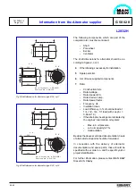
12x31.0 mm holes to be drilled acc. to MAN B&W
fig. No. V-U07B01-05-2. Holes to be reamed to-
gether with crankshaft for 32 mm fitted bolt.
50
27
Min. 230
R1
20˚
R6
R15
Max.
Ø290
Ø258
Ø250h7
-
0
0.046
Ø290
Ø400
R35
10
PCD350
Direction of rotation
Seen from fore
Fig 2 Shaft dimension for alternator, type B 16, cyl. 5 - 6 - 9
Содержание 5L28/32H
Страница 4: ......
Страница 5: ...Introduction I 00...
Страница 6: ......
Страница 8: ......
Страница 10: ......
Страница 11: ...Designation of Cylinders In Line 98 19 1607568 0 1 Page 1 1 I 00 15 0...
Страница 12: ......
Страница 18: ......
Страница 19: ...General information D 10...
Страница 20: ......
Страница 22: ......
Страница 24: ......
Страница 26: ......
Страница 30: ......
Страница 32: ......
Страница 34: ......
Страница 36: ......
Страница 37: ...Basic Diesel Engine B 10...
Страница 38: ......
Страница 44: ......
Страница 45: ...99 40 B 10 01 1 L28 32H Cross Section 1607528 5 2 Page 1 1...
Страница 46: ......
Страница 48: ......
Страница 50: ......
Страница 52: ......
Страница 54: ......
Страница 58: ......
Страница 59: ...1607566 7 1 Page 1 1 Engine Rotation Clockwise B 10 11 1 General 98 18...
Страница 60: ......
Страница 61: ...Fuel Oil System B 11...
Страница 62: ......
Страница 65: ...08028 0D H5250 94 08 12 General Fuel Oil Diagram B 11 00 0 1624468 9 4 Page 1 3 99 33 Fig 1 Fuel oil diagram...
Страница 68: ......
Страница 72: ......
Страница 74: ......
Страница 76: ......
Страница 79: ...Lubrication Oil System B 12...
Страница 80: ......
Страница 86: ......
Страница 88: ......
Страница 91: ...Cooling Water System B 13...
Страница 92: ......
Страница 98: ......
Страница 106: ......
Страница 108: ......
Страница 112: ......
Страница 113: ...Compressed Air System B 14...
Страница 114: ......
Страница 118: ......
Страница 119: ...Combustion Air System B 15...
Страница 120: ......
Страница 124: ......
Страница 126: ...Fig 1 Jet system 1639456 5 0 Page 2 2 Lambda Controller 93 44 L28 32H B 15 11 1...
Страница 127: ...Exhaust Gas System B 16...
Страница 128: ......
Страница 132: ...08028 0D H5250 94 08 12 General 1607517 7 4 Page 2 2 Water Washing of Turbocharger Turbine B 16 01 1 98 20...
Страница 136: ......
Страница 140: ......
Страница 142: ......
Страница 144: ......
Страница 146: ......
Страница 147: ...Speed Control System B 17...
Страница 148: ......
Страница 150: ......
Страница 152: ......
Страница 153: ...Monitoring Equipment B 18...
Страница 154: ......
Страница 156: ......
Страница 158: ......
Страница 159: ...Safety and Control System B 19...
Страница 160: ......
Страница 164: ......
Страница 166: ......
Страница 177: ...Foundation B 20...
Страница 178: ......
Страница 180: ......
Страница 183: ...Test running B 21...
Страница 184: ......
Страница 186: ......
Страница 187: ...Spare Parts E 23...
Страница 188: ......
Страница 190: ......
Страница 191: ...99 35 1607521 2 6 Page 1 1 Recommended Wearing Parts E 23 04 0 L28 32H...
Страница 192: ......
Страница 195: ...Tools P 24...
Страница 196: ......
Страница 200: ......
Страница 202: ......
Страница 203: ...Preservation and Packing B 25...
Страница 204: ......
Страница 206: ......
Страница 208: ......
Страница 210: ......
Страница 211: ...Alternator G 50...
Страница 212: ......
Страница 216: ......
Страница 218: ......


