

R
epair
P 6/ 10
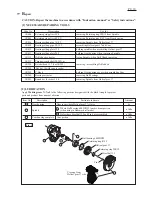
[3] DISASSEMBLY/ASSEMBLY
DISASSEMBLING
ASSEMBLING
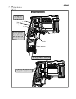
Fig. 7
Fig. 8
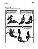
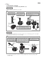
[3] -3. Helical Gear 37 and Ball bearing 6002DDW (cont.)
(4) Remove Ball bearing 6002DDW as drawn in
Fig. 7
.
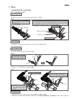
(1) Assemble Ball bearing 6002DDW to Gear housing. And then, secure it with Retaining ring R-32. Refer to
Fig. 7
.
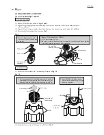
(2) Assemble Spindle and Helical gear 37 as drawn in
Fig. 8
.
1. Remove Retaining
ring R-32 with 1R005.
2. Insert Spindle into Ball
bearing 6002DDW
to use Spindle as a jig.
3. Strike the head of the re-inserted Spindle
with Plastic hammer.
Then, Ball bearing 6002DDW is removed.
Ball bearing 6002DDW
Gear
housing
Retaining
ring R-32
Spindle
1R005
Gear housing
Compression
spring 16
1. Pass Spindle through
Compression spring 16
and insert the Spindle into
Ball bearing 6002DDW.
2. Put Gear housing onto 1R035 while
aligning the inserted Spindle head with
the hole of 1R035. Set Helical gear 37 to
Spindle with the Cam portion facing to
Cam housing complete side.
3. Press 1R028 with Arbor press.
Then, Helical gear 37 is
installed on Spindle properly.
1R035
Helical gear 37
Helical gear 37
Gear housing
Spindle
1R028
Arbor press
Cam portion
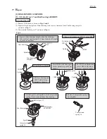
(3) Assemble Retaining ring WR-12, Steel ball 3.5 and Pin 4 to Spindle. Refer to the drawing on the upper
left
and
right
in
Fig. 6
.
Hole of 1R035
Note
: When Helical gear 37 is removed,
Ball bearing 6002DDW has damage.
Do not reuse the Ball bearing 6002DDW.