

P 2/ 10
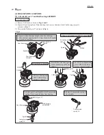
[1] NECESSARY REPAIRING TOOLS
CAUTION: Repair the machine in accordance with “Instruction manual” or “Safety instructions”.
Code No.
Description
Use for
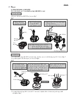
1R004
Retaining ring pliers ST-2
removing Retaining ring WR12 from Spindle
1R005
Retaining ring pliers RT-2N
removing Retaining ring R-32 from Gear housing
1R026
Bearing setting pipe 16-8.2
removing Spindle from Helical gear 37
1R028
Bearing setting pipe 20-12.2
assembling Helical gear 37 and Cam
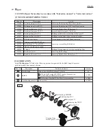
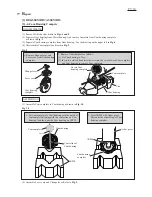
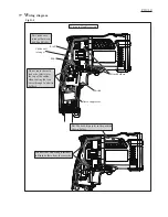
[2] LUBRICATION
Apply
Makita grease N. No.2
to the following portions designated with the black triangle to protect
parts and product from unusual abrasion.
Fig. 1
Item No.
Description
Gear housing
4g
a little
a little
a little
Gear room where Helical gear 37 rotates
Cam portion
Hole where Steel ball 3.5 and Pin 4 are assembled
Where Ball bearing 6002DDW touches drum portion
(when using in Hammer drill mode)
Cam housing complete
Spindle
Steel ball 3.5
Retaining ring WR12
Viewing from
Helical gear 37 side
Retaining ring R-32
Pin 4
Amount
Portion to lubricate
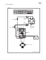
1R035
1R037
1R139
1R223
1R224
1R258
1R269
1R283
1R298
Bearing setting plate 15.2
holding spindle when assembling Helical gear 37
Bearing setting plate 20.2
holding Gear housing when removing Spindle
holding Gear housing cover when assembling Cam
Drill chuck extractor
fixing Spindle, when Drill Chuck removing
Torque wrench shaft 20-90N.m
removing / assembling Drill chuck
removing Ball bearings
Ratchet head 12.7 (For 1R223)
V block
Bearing extractor
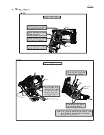
Round bar for arbor 9-50
removing Spindle from Helical gear 37
Hex bar 10 with square socket
Helical gear 37
Ball bearing 6002DDW
7a
7b
7a
7b
R
epair