8
• Refer to the tool specifications in this manual and do
not cut rebar of size or hardness that exceeds the
cutting capacity of the tool.
• Do not cut material other than rebar. Please ask the
manufacturer if you want to cut other materials.
WARNING:
• Replace damaged (chipped, broken, cracked) or
deformed blades immediately. The blade will not cut
true and may fracture or break causing serious
personal injury.
Cutting Procedure
WARNING:
•
Never use the tool without the protector in place.
Failure to do so can cause serious personal injury.
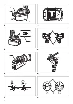
(Fig. 5)
• Protector is an equipment to prevent fragments from
being projected towards the operator. It does not
prevent a projection to the axial direction of the rebar.
Position yourself so that the protector blocks the
fragments.
• In some figures the protector is not shown, but it is for
showing the inside of the protector. Always use the
protector in place.
1. Position the rebar to be cut between the blades.
(Fig. 6)
Adjust the Stopper according to the diameter of the
rebar to be cut so that the rebar is at 90 degrees to the
blades. The Stopper supports the rebar and keeps it
perpendicular to the blades when cutting.
(Fig. 7)
WARNING:
• When cutting rebar, adjust the Stopper according to the
diameter of the rebar to be cut so that the rebar is at 90
degrees to the blades. Without this adjustment, the cut
piece may fly off and cause serious injury to the
operator or bystanders. Never fail to check the position
of the operator relative to the tool and confirm the
safety of the operator and surrounding area.
2. Position the rebar deep enough between the blades
so that it does not touch the protector.
(Fig. 8)
WARNING:
• If the rebar to be cut is not positioned fully between the
blades, the blades will be damaged; the rebar will be
ejected violently and may cause serious personal
injury.
WARNING:
• Do not cut rebar when the piece to be cut off is less
than 200 mm in length. Cutting shorter length may
cause the rebar to fly off during cut and may result in
serious personal injury.
(Fig. 9)
WARNING:
• Do not cut rebar when it is not properly supported by
the Stopper. When cutting, hold the rebar on the
Stopper side.
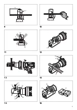
(Fig. 10, 11)
If not, the cut piece may fly
off and cause serious injury to the operator or
bystanders.
3. Push in the Switch Lock on Side A. The switch is
unlocked and the trigger can be operated.
4. Press the switch trigger to start cutting operation. The
Cutter Rod will move forward to cut the rebar. Keep
the Switch depressed until the Cutter Rod stops at the
end of its stroke.
5. Release the switch trigger when the cut is completed
and the Cutter Rod has reached the end of its stroke.
The Cutter Rod will then return automatically to its
starting position. The Cutter Rod will not return if the
stroke is not completed. Similarly the Cutter Rod will
not be able to move forward again until after it returns
completely to its starting position. Press the switch to
start the next cut, only after the Cutter Rod completely
returns to its starting position and stops.
WARNING:
• When cutting rebar of a high tensile strength the cut
piece may fly off and cause serious injury to the
operator. Wear safety glasses and confirm that the
surrounding area is safe before starting operation.
WARNING:
• Keep your hands and face away from the blades, the
moving parts and the cutting area, during operation.
Remove the Battery from the tool immediately after
use.
NOTE:
• If the temperature of the tool housing exceeds 70°C
(160°F), the tool capacity decreases. In such a case,
stop the use and allow the tool to cool down.
NOTE:
• Keep the air hole in the end of the Bar Holder clear of
dirt and debris. The air hole controls the internal
pressure and should not be obstructed.
(Fig. 12)
Rotating Function of Motor (Fig. 13)
The Motor Body can be rotated through 360 degrees, in
either direction, during operation. This feature is
particularly useful when working in awkward or narrow
areas as it allows the operator to position the tool in the
best position for easy operation.
Return Valve Operation (Fig. 14)
The function of the Return Valve is to allow the Cutter Rod
to return to the starting position if it is unable complete a
cut or becomes jammed. Loosening the return valve half
turn will release the oil pressure and allow the Cutter Rod
to return. Retighten the Return Valve once the Cutter Rod
is fully returned and before starting the next operation.
BLADES REPLACEMENT
PROCEDURE
If the cutting edges of the blades are chipped, cracked,
deformed, or damaged in any way, their cutting ability will
be reduced. Cutting under such conditions may cause
further damage and result in personal injury. The blades
should be replaced as a set immediately if any damage is
found.
WARNING:
• When replacing the blades, ensure that the Battery is
removed from the tool to prevent accidental operation.
Ensure that Blade A, on the Bar Holder and Blade B, on
the Cutter Rod are fitted in their correct respective
positions.
(Fig. 15)
1. Undo the bolts and the washers that hold Blade A and
Blade B.
Содержание XCS04
Страница 2: ...2 1 2 3 4 5 6 7 8 1 2 3 4 5 6 7 8 9 10 11 12 13 11 11 12 13 11 12 ...
Страница 3: ...3 9 10 11 12 13 14 15 16 12 14 11 12 13 15 16 17 11 18 19 20 21 22 23 24 22 25 26 27 ...
Страница 22: ...22 ...
Страница 23: ...23 ...


