Makita UG002G Скачать руководство пользователя страница 15

15 ENGLISH

Tool / battery protection system

The tool is equipped with a tool/battery protection sys-

tem. This system automatically cuts off power to the 

motor to extend tool and battery life. The tool will auto-

matically stop during operation if the tool or battery is 

placed under one of the following conditions:

Overload protection

When the battery is operated in a manner that causes 

it to draw an abnormally high current, the tool automati-

cally stops and the main power lamp blinks in green. In 

this situation, turn the tool off and stop the application 

that caused the tool to become overloaded. Then turn 

the tool on to restart.

Overheat protection

When the tool or battery is overheated, the tool stops 

automatically and the main power lamp lights up in red. 

In this case, let the tool and battery cool before turning 

the tool on again.

NOTE:

 In high temperature environment, the over-

heat protection likely to work and the tool stops 

automatically.

Overdischarge protection

When the battery capacity is not enough, the tool stops 

automatically and the main power lamp blinks in red. In 

this case, remove the battery from the tool and charge 

the battery.

Protections against other causes

Protection system is also designed for other causes 

that could damage the tool and allows the tool to stop 

automatically. Take all the following steps to clear the 

causes, when the tool has been brought to a temporary 

halt or stop in operation.

1.  Turn the tool off, and then turn it on again to 

restart.

2.  Charge the battery(ies) or replace it/them with 

recharged battery(ies).

3.  Let the machine and battery(ies) cool down.
If no improvement can be found by restoring protection 

system, then contact your local Makita Service Center.

NOTICE:


If the tool stops due to a cause 

not described above, refer to the section for 

troubleshooting.

Main power switch

WARNING:


Always turn off the main power 

switch when not in use.

To turn on the tool, press the main power switch. The 

main power lamp lights up in green. To turn off, press 

the main power switch again.
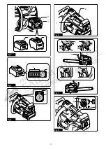
► 

Fig.5:


1.

 Main power lamp 

2.

 Main power switch

NOTE:

 The main power lamp blinks in green if the 

switch trigger is pulled under unoperatable conditions. 

The lamp blinks in one of the following conditions.


When you turn on the main power switch while 

holding down the lock-off lever and the switch 

trigger.


When you pull the switch trigger while the chain 

brake is applied.


When you release the chain brake while holding 

down the lock-off lever and pulling the switch 

trigger.

NOTE:

 This tool employs the auto power-off function. 

To avoid unintentional start up, the main power switch 

will automatically shut down when the switch trigger 

is not pulled for a certain period after the main power 

switch is turned on.

Switch action

WARNING:


For your safety, this tool is 

equipped with lock-off lever which prevents the 

tool from unintended starting. NEVER use the tool 

if it runs when you simply pull the switch trigger 

without pressing the lock-off lever. Return the 

tool to our authorized service center for proper 

repairs BEFORE further usage.

WARNING:


NEVER tape down or defeat pur-

pose and function of lock-off lever.

CAUTION:


Before installing the battery car-

tridge into the tool, always check to see that the 

switch trigger actuates properly and returns to 

the "OFF" position when released.

NOTICE:


Do not pull the switch trigger hard with-

out pressing the lock-off lever. This can cause 

switch breakage.

NOTE:

 When you keep pulling the switch trigger while 

the tool is under almost no load, the rotation speed of 

the tool decreases and the main power lamp blinks 

in green. In this case, release the switch trigger, and 

then pull the switch trigger again.

To prevent the switch trigger from being accidentally 

pulled, a lock-off lever is provided. To start the tool, 

depress the lock-off lever and pull the switch trigger. 

The tool speed increases by increasing pressure on the 

switch trigger. Release the switch trigger to stop.

► 

Fig.6:


1.

 Switch trigger 

2.

 Lock-off lever

Checking the chain brake

CAUTION:


Hold the chain saw with both 

hands when switching it on. Hold the top handle 

with your right hand, the front handle with your 

left. The guide bar and the saw chain must not be 

in contact with any object.

CAUTION:


Should the saw chain not stop 

immediately when this test is performed, the 

chain saw may not be used under any circum-

stances. Consult our authorized service center.

Содержание UG002G

Страница 1: ...äge BETRIEBSANLEITUNG 36 IT Motosega a batteria ISTRUZIONI PER L USO 51 NL Accukettingzaag GEBRUIKSAANWIJZING 66 ES Electrosierra Inalámbrica MANUAL DE INSTRUCCIONES 80 PT Motosserra a Bateria MANUAL DE INSTRUÇÕES 95 DA Akku kædesav BRUGSANVISNING 110 EL Φορητό αλυσοπρίονο ΕΓΧΕΙΡΙΔΙΟ ΟΔΗΓΙΩΝ 124 TR Akülü Ağaç Kesme KULLANMA KILAVUZU 140 ...

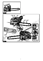
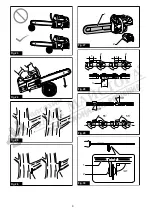
Страница 2: ...2 Fig 1 3 1 2 5 6 11 12 14 7 8 9 10 16 17 19 15 13 4 18 Fig 2 ...

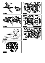
Страница 3: ...3 1 1 2 3 Fig 3 1 2 Fig 4 1 2 Fig 5 2 1 Fig 6 3 2 1 2 3 Fig 7 2 1 Fig 8 ...

Страница 4: ...4 1 Fig 9 2 3 1 Fig 10 1 Fig 11 2 1 Fig 12 1 4 2 3 4 Fig 13 1 Fig 14 1 2 Fig 15 1 Fig 16 ...

Страница 5: ...5 3 2 1 Fig 17 1 Fig 18 1 2 Fig 19 1 2 3 Fig 20 1 2 Fig 21 Fig 22 ...

Страница 6: ...6 Fig 23 Fig 24 1 2 Fig 25 Fig 26 2 1 Fig 27 2 2 1 1 3 1 Fig 28 30 30 55 55 Fig 29 1 2 Fig 30 ...

Страница 7: ...7 30 1 5 1 Fig 31 Fig 32 Fig 33 Fig 34 1 2 Fig 35 1 2 Fig 36 1 2 Fig 37 ...

Страница 8: ...r continuing program of research and development the specifications herein are subject to change without notice Specifications may differ from country to country 1 Weight without the saw chain guide bar guide bar cover oil and battery cartridge s 2 The lightest and heaviest combination of weight according to EPTA Procedure 01 2014 The weight may differ depending on the attachment s including the b...

Страница 9: ... mm 337 mm Pitch 3 8 Gauge 1 3 mm Type Sprocket nose bar Sprocket Number of teeth 6 Pitch 3 8 Saw chain type 80TXL Number of drive links 38 46 51 Guide bar Guide bar length 250 mm 300 mm 350 mm Cutting length 232 mm 272 mm 342 mm Pitch 0 325 Gauge 1 1 mm Type Sprocket nose bar Sprocket Number of teeth 7 Pitch 0 325 Saw chain type 25AP Number of drive links 60 Guide bar Guide bar length 250 mm Cutt...

Страница 10: ... It is also suitable for tree service Noise The typical A weighted noise level determined accord ing to EN62841 1 and EN ISO 11681 2 as applicable Model UC002G Sound pressure level LpA 90 dB A Sound power level LWA 101 dB A Uncertainty K 3 dB A Model UC003G Sound pressure level LpA 90 dB A Sound power level LWA 101 dB A Uncertainty K 3 dB A Model UC004G Sound pressure level LpA 90 dB A Sound power...

Страница 11: ...imb that is under tension be alert for spring back When the tension in the wood fibres is released the spring loaded limb may strike the operator and or throw the chain saw out of control 7 Use extreme caution when cutting brush and sap lings The slender material may catch the saw chain and be whipped toward you or pull you off balance 8 Carry the chain saw by the front handle with the chain saw s...

Страница 12: ...elling techniques are extremely dangerous and require special training The operators must be trained to become familiar with safety equipment usage and climbing techniques Always use the appropriate belts ropes and carabiners when working in trees Always use restraining equipment for both the operator and the saw 2 Perform cleaning and maintenance before storage in accordance with the instruction ...

Страница 13: ...ing possible burns and even a breakdown 6 Do not store and use the tool and battery car tridge in locations where the temperature may reach or exceed 50 C 122 F 7 Do not incinerate the battery cartridge even if it is severely damaged or is completely worn out The battery cartridge can explode in a fire 8 Do not nail cut crush throw drop the battery cartridge or hit against a hard object to the bat...

Страница 14: ...ving battery cartridge Failure to hold the tool and the battery cartridge firmly may cause them to slip off your hands and result in damage to the tool and battery cartridge and a personal injury Fig 3 1 Red indicator 2 Button 3 Battery cartridge To remove the battery cartridge slide it from the tool while sliding the button on the front of the cartridge To install the battery cartridge align the ...

Страница 15: ...er lamp blinks in green if the switch trigger is pulled under unoperatable conditions The lamp blinks in one of the following conditions When you turn on the main power switch while holding down the lock off lever and the switch trigger When you pull the switch trigger while the chain brake is applied When you release the chain brake while holding down the lock off lever and pulling the switch tri...

Страница 16: ... chain with bare hands Always wear gloves when handling the saw chain Installing or removing saw chain CAUTION The saw chain and the guide bar are still hot just after the operation Let them cool down enough before carrying out any work on the tool CAUTION Carry out the procedure of install ing or removing saw chain in a clean place free from sawdust and the like Installing the saw chain To instal...

Страница 17: ... Saw chain is automatically lubricated when the tool is in operation Check the amount of remaining oil in the oil tank periodically through the oil inspection window Fig 19 1 Oil tank cap 2 Oil inspection window To refill the tank lay the chain saw on its side then push the button on the oil tank cap so that the button on the other side stands up and then remove the oil tank cap by turning it The ...

Страница 18: ... cutters Different cutter angles cause the chain to run roughly and unevenly accelerate wear and lead to chain breaks Use a suitable round file so that the proper sharp ening angle is kept against the teeth Chain blade 90PX 55 Chain blade 91PX 55 Chain blade 80TXL 55 Chain blade 25AP 55 File and file guiding Use a special round file optional accessory for saw chains to sharpen the chain Normal rou...

Страница 19: ...the tool run it under no load to lubri cate the saw chain and guide bar 3 Cover the guide bar with the guide bar cover 4 Empty the oil tank Instructions for periodic maintenance To ensure long life prevent damage and ensure the full functioning of the safety features the following maintenance must be performed regularly Warranty claims can be recognized only if this work is performed regularly and...

Страница 20: ... authorized service center in your region for repair The main power lamp is blinking in green Switch trigger is pulled under an unoperat able condition Pull the switch trigger after the main power switch is turned on and the chain brake is released Chain does not stop even the chain brake is activated Stop the tool immediately The brake band is worn down Ask the authorized service center in your r...

Отзывы: