22 ENGLISH
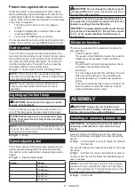
Changing the collet cone
CAUTION:
Use the correct size collet cone for
the trimmer bit which you intended to use.
CAUTION:
Do not tighten the collet nut without
installing a trimmer bit, or the collet cone may break.
1.
Loosen the collet nut and remove.
2.
Replace the installed collet cone with desired collet cone.
3.
Reinstall collet nut.
►
Fig.9:
1.
Collet cone
2.
Collet nut
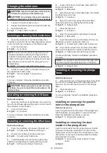
Installing or removing the trimmer base
1.
Open the lock lever of the trimmer base, then
insert the tool into the trimmer base aligning the groove
on the tool with the protrusion on the trimmer base.
2.
Close the lock lever.
►
Fig.10:
1.
Lock lever
NOTE:
You can use the trimmer base (resin) as an
optional accessory as shown in the figure. When
using the trimmer base (resin), loosen or tighten the
thumb nut instead of opening or closing the lock lever.
Align the rack on the tool with the spur gear on the
trimmer base.
►
Fig.11:
1.
Thumb nut
2.
Rack
3.
Spur gear
3.
Attach the dust nozzle to the trimmer base, and
then tighten the thumb screw.
►
Fig.12:
1.
Dust nozzle
2.
Thumb screw
►
Fig.13
To remove the base, follow the installation procedure
in reverse.
CAUTION:
When using the tool with the trim-
mer base, be sure to install the dust nozzle on the
trimmer base.
Installing or removing the tilt base
Optional accessory
1.
Open the lock lever of the tilt base, then insert the
tool into the tilt base aligning the groove on the tool with
the protrusion on the tilt base.
2.
Close the lock lever.
►
Fig.14:
1.
Lock lever
To remove the base, follow the installation procedure
in reverse.
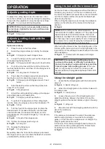
Installing or removing the offset base
Optional accessory
1.
Press the shaft lock, then loosen the collet nut.
►
Fig.15:
1.
Collet nut
2.
Shaft lock
3.
Wrench
2.
Remove the collet nut and the collet cone.
►
Fig.16:
1.
Collet nut
2.
Collet cone
3.
Install the pulley onto the tool by pressing the
shaft lock and tightening the pulley with the wrench.
►
Fig.17:
1.
Wrench
2.
Pulley
3.
Shaft lock
4.
Loosen the screws on the base plate, and then
remove the base plate.
►
Fig.18:
1.
Base plate
5.
Open the lock lever of the offset base, then attach
the offset base to the tool.
►
Fig.19:
1.
Lock lever
6.
Mount the belt to the pulley with a stick like a
slotted screwdriver by rotating the belt manually.
►
Fig.20:
1.
Pulley
2.
Belt
7.
Close the lock lever.
►
Fig.21:
1.
Lock lever
8.
Attach the base plate by tightening the screws.
►
Fig.22:
1.
Base plate
9.
Insert the collet cone and the trimmer bit into the
offset base, and then tighten the collet nut.
►
Fig.23:
1.
Trimmer bit
2.
Collet nut
3.
Collet cone
10.
Insert the hex wrench into the hole of the offset
base, and then tighten the collet nut with the wrench.
►
Fig.24:
1.
Collet nut
2.
Wrench
3.
Hex wrench
To remove the base, follow the installation procedure
in reverse.
NOTE:
You can also mount the belt to the pulley with
-
out removing the base plate as shown in the figure.
►
Fig.25:
1.
Pulley
2.
Belt
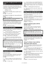
Installing or removing the plunge
base
Optional accessory
1.
Open the lock lever of the plunge base, then insert
the tool into the plunge base all the way aligning the
groove on the tool with the protrusion on the plunge
base.
2.
Close the lock lever.
►
Fig.26:
1.
Lock lever
To remove the base, follow the installation procedure
in reverse.
Installing or removing the parallel
ruler on the plunge base
Optional accessory
Insert the guide bars into the holes in the plunge base,
and then tighten the wing bolts. To remove the ruler,
follow the installation procedure in reverse.
►
Fig.27:
1.
Wing bolt
2.
Guide bar
Installing or removing the dust
nozzle on the plunge base
Insert the dust nozzle into the plunge base so that the
protrusion on the dust nozzle fits in the notch in the
plunge base, and then tighten the thumb screw on the
dust nozzle. To remove the nozzle, follow the installa-
tion procedure in reverse.
►
Fig.28:
1.
Protrusion
2.
Dust nozzle
3.
Thumb
screw
►
Fig.29
Содержание RT001G
Страница 2: ...2 2 3 1 Fig 1 1 2 Fig 2 1 2 Fig 3 1 Fig 4 1 Fig 5 1 2 3 4 5 Fig 6 1 4 2 3 1 Fig 7 1 Fig 8 ...
Страница 3: ...3 1 2 Fig 9 1 Fig 10 1 3 2 Fig 11 2 1 Fig 12 Fig 13 1 Fig 14 ...
Страница 4: ...4 1 2 3 Fig 15 1 2 Fig 16 1 2 3 Fig 17 1 Fig 18 1 Fig 19 2 1 Fig 20 1 Fig 21 1 Fig 22 ...
Страница 5: ...5 1 2 3 Fig 23 1 2 3 Fig 24 2 1 Fig 25 1 Fig 26 1 2 Fig 27 1 2 3 Fig 28 Fig 29 ...
Страница 6: ...6 1 2 Fig 30 1 Fig 31 1 2 Fig 32 1 2 3 Fig 33 1 2 Fig 34 1 2 3 Fig 35 1 Fig 36 1 2 Fig 37 ...
Страница 7: ...7 1 Fig 38 1 Fig 39 1 Fig 40 1 Fig 41 Fig 42 1 3 2 Fig 43 2 1 Fig 44 1 1 Fig 45 ...
Страница 8: ...8 1 Fig 46 Fig 47 A Fig 48 1 Fig 49 1 Fig 50 2 1 Fig 51 1 2 Fig 52 Fig 53 ...
Страница 9: ...9 1 2 3 4 5 6 Fig 54 Fig 55 1 Fig 56 1 2 Fig 57 1 2 3 Fig 58 1 Fig 59 1 2 Fig 60 Fig 61 ...
Страница 10: ...10 1 2 Fig 62 1 2 Fig 63 1 2 Fig 64 1 2 3 4 Fig 65 1 Fig 66 Fig 67 1 2 Fig 68 ...
Страница 11: ...11 Fig 69 Fig 70 A Fig 71 1 2 3 Fig 72 Fig 73 1 Fig 74 ...
Страница 12: ...12 1 4 2 3 Fig 75 1 2 3 Fig 76 1 Fig 77 1 2 1 2 Fig 78 Fig 79 1 Fig 80 2 1 Fig 81 1 Fig 82 ...
Страница 13: ...13 1 Fig 83 1 2 1 2 Fig 84 D L1 L2 A Fig 85 L2 L1 D A R Fig 86 θ θ θ D L2 L1 A Fig 87 Fig 88 Fig 89 Fig 90 ...
Страница 14: ...14 Fig 91 Fig 92 θ θ θ D L2 L1 A Fig 93 Fig 94 Fig 95 Fig 96 Fig 97 Fig 98 ...
Страница 16: ...16 25 24 30 28 29 31 32 Fig 101 ...
Страница 182: ...182 ...
Страница 183: ...183 ...


