21 ENGLISH
Protections against other causes
Protection system is also designed for other causes
that could damage the tool and allows the tool to stop
automatically. Take all the following steps to clear the
causes, when the tool has been brought to a temporary
halt or stop in operation.
1. Turn the tool off, and then turn it on again to
restart.
2. Charge the battery(ies) or replace it/them with
recharged battery(ies).
3. Let the tool and battery(ies) cool down.
If no improvement can be found by restoring protection
system, then contact your local Makita Service Center.
Switch action
To turn on the tool, press the lock/unlock button. The
tool turns into the standby mode. To start the tool, press
the start/stop button in the standby mode. To stop the
tool, press the start/stop button again. The tool turns
into the standby mode. To turn off the tool, press the
lock/unlock button in the standby mode.
►
Fig.3:
1.
Lock/unlock button
2.
Start/stop button
NOTE:
If the tool is left for 10 seconds without any
operation in the standby mode, the tool automatically
turns off and the lamp goes off.
NOTE:
You can also stop and turn off the tool by
pressing the lock/unlock button while the tool is
operating.
Lighting up the front lamp
CAUTION:
Do not look in the light or see the
source of light directly.
To turn on the lamp, press the lock/unlock button. To
turn off the lamp, press the lock/unlock button again.
NOTICE:
When the tool is overheated, the lamp
blinks. Cool down the tool fully before operating
the tool again.
NOTE:
Use a dry cloth to wipe the dirt off the lens of
the lamp. Be careful not to scratch the lens of lamp, or
it may lower the illumination.
►
Fig.4:
1.
Lamp
Speed adjusting dial
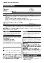
The rotation speed of the tool can be changed by turn
-
ing the speed adjusting dial. The table below shows
the number on the dial and the corresponding rotation
speed.
►
Fig.5:
1.
Speed adjusting dial
Number
Speed
1
10,000 min
-1
2
15,000 min
-1
3
21,000 min
-1
4
26,000 min
-1
5
31,000 min
-1
CAUTION:
Do not change the rotation speed
during operation.
Otherwise unexpected reaction of
the tool may cause an injury.
NOTICE:
If the tool is operated continuously at
low speed for a long time, the motor will get over-
loaded, resulting in tool malfunction.
NOTICE:
The speed adjusting dial can be turned
only as far as 5 and back to 1. Do not force it past
5 or 1, or the speed adjusting function may no
longer work.
Electronic function
The tool is equipped with the electronic functions for
easy operation.
•
Constant speed control
The speed control function provides the constant
rotation speed regardless of load conditions.
•
Soft start
The soft-start function minimizes start-up shock,
and makes the tool start smoothly.
•
Soft brake
The tool stops gently with the soft brake. The soft
brake prevents damage to the workpiece due
to recoil and allows you to start next operation
earlier.
If the tool consistently fails to stop the trimmer bit
after the switch is turned off, have the tool ser
-
viced at a Makita service center.
ASSEMBLY
CAUTION:
Always be sure that the tool is
switched off and the battery cartridge is removed
before carrying out any work on the tool.
Installing or removing trimmer bit
NOTICE:
Do not tighten the collet nut without
installing a trimmer bit, or the collet cone may
break.
Insert the trimmer bit all the way into the collet cone.
Press the shaft lock and tighten the collet nut with the
wrench.
►
Fig.6:
1.
Shaft lock
2.
Loosen
3.
Tighten
4.
Wrench
5.
Collet nut
You can also tighten the collet nut securely with the two
wrenches.
►
Fig.7:
1.
Wrench
2.
Loosen
3.
Tighten
4.
Collet nut
To remove the trimmer bit, follow the installation proce
-
dure in reverse.
NOTE:
The shaft lock may not return to the original
position when you tighten the collet nut in the instal-
lation of the trimmer bit. The shaft lock returns to the
original position when you start the tool.
►
Fig.8:
1.
Shaft lock
Содержание RT001G
Страница 2: ...2 2 3 1 Fig 1 1 2 Fig 2 1 2 Fig 3 1 Fig 4 1 Fig 5 1 2 3 4 5 Fig 6 1 4 2 3 1 Fig 7 1 Fig 8 ...
Страница 3: ...3 1 2 Fig 9 1 Fig 10 1 3 2 Fig 11 2 1 Fig 12 Fig 13 1 Fig 14 ...
Страница 4: ...4 1 2 3 Fig 15 1 2 Fig 16 1 2 3 Fig 17 1 Fig 18 1 Fig 19 2 1 Fig 20 1 Fig 21 1 Fig 22 ...
Страница 5: ...5 1 2 3 Fig 23 1 2 3 Fig 24 2 1 Fig 25 1 Fig 26 1 2 Fig 27 1 2 3 Fig 28 Fig 29 ...
Страница 6: ...6 1 2 Fig 30 1 Fig 31 1 2 Fig 32 1 2 3 Fig 33 1 2 Fig 34 1 2 3 Fig 35 1 Fig 36 1 2 Fig 37 ...
Страница 7: ...7 1 Fig 38 1 Fig 39 1 Fig 40 1 Fig 41 Fig 42 1 3 2 Fig 43 2 1 Fig 44 1 1 Fig 45 ...
Страница 8: ...8 1 Fig 46 Fig 47 A Fig 48 1 Fig 49 1 Fig 50 2 1 Fig 51 1 2 Fig 52 Fig 53 ...
Страница 9: ...9 1 2 3 4 5 6 Fig 54 Fig 55 1 Fig 56 1 2 Fig 57 1 2 3 Fig 58 1 Fig 59 1 2 Fig 60 Fig 61 ...
Страница 10: ...10 1 2 Fig 62 1 2 Fig 63 1 2 Fig 64 1 2 3 4 Fig 65 1 Fig 66 Fig 67 1 2 Fig 68 ...
Страница 11: ...11 Fig 69 Fig 70 A Fig 71 1 2 3 Fig 72 Fig 73 1 Fig 74 ...
Страница 12: ...12 1 4 2 3 Fig 75 1 2 3 Fig 76 1 Fig 77 1 2 1 2 Fig 78 Fig 79 1 Fig 80 2 1 Fig 81 1 Fig 82 ...
Страница 13: ...13 1 Fig 83 1 2 1 2 Fig 84 D L1 L2 A Fig 85 L2 L1 D A R Fig 86 θ θ θ D L2 L1 A Fig 87 Fig 88 Fig 89 Fig 90 ...
Страница 14: ...14 Fig 91 Fig 92 θ θ θ D L2 L1 A Fig 93 Fig 94 Fig 95 Fig 96 Fig 97 Fig 98 ...
Страница 16: ...16 25 24 30 28 29 31 32 Fig 101 ...
Страница 182: ...182 ...
Страница 183: ...183 ...


