12
Table saw mode
1
2
012208
Miter saw mode
1
012209
To install the blade cover when using in the table saw mode
(bench mode), turn the turn base to 0°miter angle (see the
section titled "Adjusting miter angle") and place the blade
cover on the turn table so that the blade cover is centered
over the slit for the blade entrance in the turn table and then
lock the handle in the lowest position by fully pushing in the
stopper pin as shown in the figure.
NOTE:
•
When using the tool in the table saw mode (bench
mode), make sure that the blade cover is installed
on the turn table.
Securing workpiece
Whenever possible, secure the workpiece with the
optional vise. If you must use your hand to hold the
workpiece, then it must be done firmly and securely so
as not to lose control of the workpiece. Your hand and
arm must be kept well away from the blade area
(100mm minimum). Squeeze the workpiece firmly
against the guide fence with your fingers held over the
top of the guide fence. The workpiece must also rest
steadily on the turn base.
WARNING:
•
Never use your hand to hold the workpiece that
requires your hand to be any closer than 100mm
from the blade area. In this case, always use the
optional vise to secure the workpiece. After any
cutting operation, raise the blade gently. Never
raise the blade until it has come to a complete stop.
Serious injury may result.
CAUTION:
•
When cutting long workpieces, use supports that
are as high as the top surface level of the turn base.
Do not rely solely on the vertical vise and/or
horizontal vise (optional) to secure the workpiece.
Thin material tends to sag. Support workpiece over
its entire length to avoid blade pinch and possible
KICKBACK.
1
2
001549
Sub-fence (for European countries only)
1
015064
This tool is equipped with the sub-fence. Usually position
the sub-fence inside. However, when performing left
bevel cuts, flip it outward.
CAUTION:
•
When performing left bevel cuts, flip the sub-fence
outward. Otherwise, it will contact the blade or a part of
the tool, causing possible serious injury to the operator.
Vertical vise
4
3
1
2
6
5
015126
The vertical vise can be installed in two positions on
either the left or right side of the guide fence. Insert the
vise rod into the hole in the guide fence or the holder
assembly and tighten the screw to secure the vise rod.
Position the vise arm according to the thickness and
shape of the workpiece and secure the vise arm by
1. Vise arm
2. Vise rod
3. Guide fence
4. Holder
5. Vise knob
6. Screw
1. Sub-fence
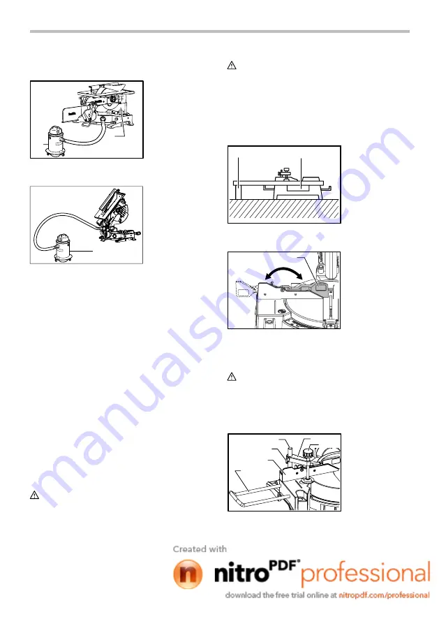
1. Support
2. Turn base
1. Vacuum cleaner
1. Vacuum cleaner
2. Blade cover


