
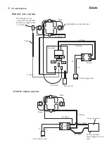
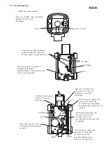

Circuit diagram
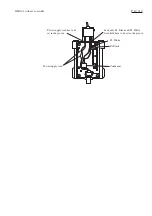
HM1202C with controller
CT1
CT3
CT2
CT4
CT5
1
4
3
6
Switch
Tube
This terminal is to be
connected to brush holder
mounted on opposite side
of control dial.
Brush holder on control dial side
>
Controller
F2. White
r3. White
F1. Black
r1. Red
P1.
P2.
r2. Black
Black
Black
Power supply cord
Pick up coil
HM1202 without controller
Black
1
4
3
6
Power supply cord
Switch
P1.
P2.
Noise suppressor
F2. White
F1. Black
C2. White
C1. White
In some countries,
Noise suppressor is not
used.
Black
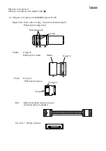
P 12 / 14


