manualshive.com logo in svg
background image

Handling

<1> Necessary repair tools
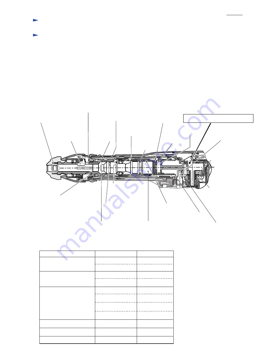
<2> Lubrication

Refer to instruction manual for handling of the tool and follow the instructions.

Apply a tube (30g) of Makita grease R No. 00 in total to the portions designated by arrows as shown below.
Also apply a little bit of Makita grease N No.2 to the portions by designated by circles.

(Code No.)

<3> Fastening torque for screws/bolts

Fasten various screws/bolts of the tool with specified torque as shown below.

M5x20 Pan head screws 

5x25 Tapping screws 

Handle

Screws/bolts 

Position in use

Fastening torque

Handle

1.8 up to 3.5 N.m.

Crank cap

1.8 up to 3.5 N.m.

1R003
1R269
1R034
1R005
1R225
1R214

Retaining ring pliers ST-2N 250mm for external ring
Bearing extractor
Bearing setting plate 12.2
Retaining ring pliers RT-2N 250mm for internal ring
Bearing extractor
Taper sleeve

(Tool Name)

Repair

2.5 up to 3.0 N.m

Motor housing

2.5 up to 3.0 N.m

4x18 Tapping screws 

Strain relief

1.3 up to 1.8 N.m

Rear cover

1.3 up to 1.8 N.m

Brush holder cover

1.3 up to 1.8 N.m

Switch box

1.3 up to 1.8 N.m

Crank housing cover

M5x25 Hex. socket head bolt

4.9 up to 7.4 N.m

Barrel

M6x30 Hex. socket head bolt

7.8 up to 12.0 N.m

Fan

M6 Hex. nut

1.8 up to 3.7 N.m

Inside lip of tool holder cap
: 0.5g

The remaining Makita grease R. No.00 (25.0g):
In the crank room

Contact area of tool retainer
and bull point installed: 0.5g

Contact area of urethane ring 28
and Flat washer 29: 0.1g

Surface of tool holder: 0.2g

Surface of
pin 8: 0.2g

Contact area of piston and
crank shaft complete: 0.2g

Contact area of crank shaft 
complete and flat washer 14: 0.1g

Surface of 
o-ring 38: 0.2g

Surface of 
o-ring 24: 0.5g

Surface of 
o-ring 24: 0.2g

Surface of 
o-ring 26: 0.2g

Contact area of rubber ring 20
and cup washer 23: 0.2g

P 2 /14

Surface of urethane ring
and tool holder: 0.1g

Surface of striker: 3.0g

Inside of sleeve: 0.1g

Contact area of flat washer 14 and 
crank housing complete: 0.1g

Engaging area of gears of armature and
crank shaft complete: 0.2g

Surface of steel ball 4.8: 1.0g

Surface of o-ring 23 and
fluoride ring 28: 1.0g

Contact area of slide sleeve
and cylinder 32: 0.2g

Contact area of cup washer
and guide ring: 0.2g

Содержание HM0860C

Страница 1: ...hown may differ from country to country P 1 14 Dimensions mm Width W Height H Length L 223 8 3 4 99 3 7 8 454 17 7 8 Blows per min bpm min Protection from electric shock Net weight Kg lbs Cord length...

Страница 2: ...Brush holder cover 1 3 up to 1 8 N m Switch box 1 3 up to 1 8 N m Crank housing cover M5x25 Hex socket head bolt 4 9 up to 7 4 N m Barrel M6x30 Hex socket head bolt 7 8 up to 12 0 N m Fan M6 Hex nut...

Страница 3: ...Ring spring 25 from tool holder using Retaining ring pliers ST 2N 1R003 And then remove Flat washer 28 Urethane ring 28 and Chuck ring from Tool holder 4 Remove two Tool retainers from Tool holder by...

Страница 4: ...k ring to Change ring as in Fig 5 so that the depressions of Lock ring can face the direction of bit side 2 Put Steel ball 4 8 4 pcs in the four grooves of Tool holder and depressions of Lock ring Not...

Страница 5: ...fasten Crank housing to Motor housing complete Armature assembly will be removed from Motor housing complete together with Crank housing So remove Armature assembly from the Crank housing by knocking...

Страница 6: ...per round bar as illustrated in Fig 11 1 Put Impact bolt into Tool holder Be sure to place Impact bolt as illustrated in Fig 12 because it is not reversible when assembled to Tool holder 2 Set Flat wa...

Страница 7: ...g complete Crank housing cover side of Crank housing complete Bearing setting plate table of arbor press Fluoride ring 28 can be removed from Impact bolt using slotted driver When installing Fluoride...

Страница 8: ...003 Fig 17 4 Remove Compression spring 37 and Ring 36 by removing Ring spring 34 from Cylinder using Retaining ring S pliers 1R003 Fig 18 M6x30 hex socket head bolts Crank housing complete Barrel Fig...

Страница 9: ...etal portion Plastic portion Rubber ring 20 Cup washer 23 Guide ring Cylinder Bit side Crank housing side Bit side Crank housing side Bit side Crank housing side 3 Insert the assembled Cylinder sectio...

Страница 10: ...out and remove Pin 28 from Piston 1 Insert Pin 28 into Piston and Connecting rod and then set O ring 26 onto the groove of Piston Fig 24 Fig 25 M5x20 pan head screws 4 pcs Crank cap Bit side Bit side...

Страница 11: ...ote Take care not to lose Leaf spring in the Switch box 3 Remove Switch from Switch box 2 Install Switch box with Switch into Switch lever in Handle Note Do this step while moving Switch lever to righ...

Страница 12: ...lead holder of Motor housing as Fig 33 Handle Motor housing Motor housing Brush holders Pass the lead wire red for connecting with Brush holder between bosses and wall of Motor housing as Fig 32 Lead...

Страница 13: ...of Controller for 220 240V white for 115 127V Lead wire black of controller Clamping lead wires of Field Terminal for carbon brush detection Controller Connector Terminal block Power supply cord Pick...

Страница 14: ...inting upwards as Fig 34 This will allow the old grease coming down to the Crank housing 3 Wipe up the old grease gathered in Crank housing with cloth 4 Put the fresh grease into the Crank housing and...

Отзывы: