P 11/ 14
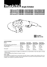
Fig. D-1
C
ircuit diagram
Black
White
Orange
Blue
Brown
Purple
Color index of lead wires' sheath
For High voltage area where Noise suppression is required
Field
For Low voltage area where Noise suppression is required
or
For areas where Noise suppression is not required
Field
(4)
(20)
(20)
(3)
(2)
Choke coil
(5)
(20)
(20)
White for some countries
(2)
(2) Noise suppressor
(3) Terminal block
(4) Switch
(5) Power supply cord
(20) Brush holder
(D) Choke coil
(2) Noise suppressor
(3) Terminal block
(4) Switch
(5) Power supply cord
(20) Brush holder
(3)
(4)
(5)
Circuit of Switch
Black
White
Orange
Blue
Brown
Purple
Color index of lead wires' sheath
1
2
Circuit of Switch
1
2
White for some countries
Black for some
countries
Black for some
countries
18 AWG
*
*
AWG: American Wire Gauge
18 AWG
*
18 AWG
*
20 AWG
*
20 AWG
*
18 AWG
*
18 AWG
*
18 AWG
*
18 AWG
*
20 AWG
*
20 AWG
*
18 AWG
*
*
AWG: American Wire Gauge
Insulated connector M3.5
Insulated connector M3.5
18 AWG
*
18 AWG
*
Insulated connector M3.5
Insulated connector M3.5
(if used)