background image

29

COVER

INNER
ELEMENT

OUTER
ELEMENT

1. Urethane Foam Element

Wash and clean the urethane foam with detergent. After cleaning, dry it.
Clean the urethane foam element every 50 hours.

2. Paper element

Clean by tapping gently to remove dirt and blow off dust.
Never use oil. Clean the paper element every 50 hours of operation, and
replace element set every 200 hours.

Clean and replace air cleaner elements more often when operating in dusty
environments.

Do not wash elements with
kerosene, gasoline or oil.

CAUTION

A dirty air cleaner element will cause
starting difficulty, power loss, engine mal-
functions, and shorten engine life
extremely. Always keep the air cleaner
element clean.

(Model G4100R, G4101R, G6100R, G6101R)

CLEANING AND ADJUSTING
SPARK PLUG

(a) If the plug is contaminated with car-

bon, remove it using a plug cleaner or
wire brush.

(b) Adjust the electrode gap

.

ELECTRODE GAP

Electrode gap

Model

Spark plug

G2800R
G4100R
G4101R

NGK BR6HS

Electrode gap

0.02 to 0.03 in.

(0.6 to 0.7 mm)

G6100R
G6101R

NGK BR6ES

0.03 in.

(0.7 to 0.8 mm)

G28R-G61R  米国取説GU2016  05.1.26  11:15 AM  ページ29

Содержание G2800R

Страница 1: ...ISSUE EMD GU2016 3ZZ9020166 GENERATOR INSTRUCTIONS FOR USE アメリカ ...

Страница 2: ...level A lower Air Index level represents cleaner exhaust from an engine The period of time in hours that the Air Index level is measured is known as the durability period Depending on the size of the engine a selection of time periods can be used to measure the Air Index level see below Descriptive Term Applicable to Emissions Durability Period Moderate 50 hours engine from 0 to 80 cc 125 hours en...

Страница 3: ...g System i Carburetor and internal parts and or pres sure regulator or fuel injection system ii Air fuel ratio feedback and control system if applicable iii Cold start enrichment system if applica ble iv Regulator assy gaseous fuel if applica ble 2 Air Induction System i Intake manifold if applicable ii Air filter 3 Ignition System i Spark plugs ii Magneto or electronic ignition system iii Spark a...

Страница 4: ...nance records covering the performance of regular maintenance in the event questions arise These receipts and maintenance records should be transferred to each subsequent owner of the engine MAKITA reserves the right to deny warranty coverage if the engine has not been prop erly maintained Warranty claims will not be denied however solely because of the lack of required maintenance or failure to k...

Страница 5: ... COVERAGE The 2005 and later engines are warranted for two years If any emission related part on your engine is defective the part will be repaired or replaced by MAKITA OWNER S WARRANTY RESPONSIBILITIES As the engine owner you are responsible for the performance of the required mainte nance listed in your Owner s Manual MAKITA recommends that you retain all receipts covering maintenance on your e...

Страница 6: ...ostic labor performed at an authorized warranty station which leads to the determination that a warranted emission related part is defective Any warranted part which is not scheduled for replacement as required maintenance or which is scheduled only for regular inspection to the effect of repair or replace as necessary shall be warranted for the warranty period Any warranted part which is schedule...

Страница 7: ... factory authorized warranty station c Failure to use recommended fuel as specified in the 2005 and later Owner s Manual d Repairs and diagnosis performed outside of an authorized warranty station e Use of parts which are not authorized by MAKITA MAINTENANCE SCHEDULE The engine owner is responsible for having all scheduled inspection and maintenance services performed at the intervals specified in...

Страница 8: ...iate loca tion where the required warranty services are to be performed A list of the Factory Service Center locations and phone numbers are provided below for your convenience 41850 Christy Street Fremont CA 94538 5107 510 657 9881 1421 N Clovis Ave Ste 112 Fresno CA 93727 209 252 5166 14930 Northam Street La Mirada CA 90638 5753 714 522 8088 1970 Fulton Avenue Sacramento CA 95825 916 482 5197 14...

Страница 9: ...ccording to instructions Do not operate the generator before you have read and under stood the instructions Failure to do so could result in death per sonal injury or equipment damage WARNING Indicates a strong possibility of severe personal injury loss of life and equip ment damage if instructions are not followed CAUTION Indicates a possibility of personal injury or equipment damage if instructi...

Страница 10: ... COMPONENTS 5 4 PRE OPERATION CHECKS 6 5 OPERATING PROCEDURES 11 6 WATTAGE INFORMATION 24 7 SPARK ARRESTER 25 8 MAINTENANCE SCHEDULE 26 9 HOW TO MAINTENANCE 28 10 PREPARATION FOR STORAGE 31 11 TROUBLESHOOTING 32 12 WIRING DIAGRAM 33 13 OPTIONAL PARTS 38 ...

Страница 11: ...r 3 feet away from any structure or building during use If the generator must be used indoors the area must be well ventilated and extreme caution must be taken regarding the discharge of exhaust gases Do not enclose the generator nor cover it with a box The generator has a built in forced air cooling system and may become over heated if it is enclosed If generator has been covered to protect it f...

Страница 12: ...e followed during each and every use Failure to do so can be fatal Do not contact the generator to a commercial power line Connection to a commercial power line may short circuit the generator and ruin it or cause electric shock hazard Use the transfer switch for connecting to domestic cir cuit No smoking while handling the battery The battery emits flammable hydrogen gas which can explode if expo...

Страница 13: ...tions given on labels and warnings Keep all instruction manuals and literature in a safe place for future reference Use only LISTED extension cords When a tool or appliance is used outdoors use only extension cords marked For Outdoor Use Extension cords when not in use should be stored in a dry and well ventilated area Always switch off generator s no fuse breaker and disconnect tools or appli anc...

Страница 14: ...nleaded gasoline Fuel tank capacity 3 17 US gal 12 0 liter Rated continu ous operation Approx 9 0 hours Starting system Recoil Dimension Length 22 4 in 570 mm 24 4 in 620 mm 26 8 in 680 mm Width 16 1 in 410 mm 17 7 in 450 mm 18 5 in 470 mm High 19 3 in 490 mm 21 3 in 540 mm 24 4 in 619 mm Dry weight Electric start type 21 8 lb 48 kg 27 2 lb 60 kg 28 8 lb 63 5 kg 35 3 lb 78 kg 37 0 lb 81 5 kg 5 68 ...

Страница 15: ...PLUG OILGAUGE OIL FILLER KEY SWITCH Electric starter type CHOKE KNOB AIR CLEANER RECOIL STARTER OIL SENSOR AC RECEPTACLE MUFFLER NO FUSE BREAKER TANK CAP DC CIRCUIT BREAKER EARTH GROUND TERMINAL DC OUTPUT TERMINAL VOLTMETER FULL POWER SWITCH IDLE CONTROL SWITCH ...

Страница 16: ...the oil filler cap when checking oil level Change oil if contaminated See How To Maintenance Oil capacity Model Upper level G2800R 0 17 US gal 0 65 liter G4100R G4101R 0 26 US gal 1 0 liter G6100R G6101R 0 32 US gal 1 2 liter Recommended engine oil Use 4 stroke automotive detergent oil of API service class SE or higher grade SG SH or SJ is recommended SAE 10W 30 or 10W 40 is recommended for genera...

Страница 17: ...01R 5 68 US gal 21 5 liter 7 TANK CAP FUEL FILTER SCREEN Do not refuel while smoking or near open flame or other such potential fire hazards Otherwise fire accident may occur CHECK ENGINE FUEL Make sure you review each warning in order to prevent fire hazard Do not refill tank while engine is running or hot Close fuel cock before refueling with fuel Be careful not to admit dust dirt water or other...

Страница 18: ...sure you review each warning in order to prevent fire hazard Keep area clear of in flammables or other hazardous materials Keep generator at least 3 feet 1 meter away from buildings or other structures Only operate generator in a dry well ventilated area Keep exhaust pipe clear of foreign objects Keep generator away from open flame No smoking Keep generator on a stable and level surface Do not blo...

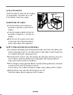
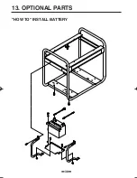
Страница 19: ...g battery connect the positive cable first and then the negative cable to the battery Be careful not to short battery cables When dismounting battery disconnect negative cable first RED CABLE To positive terminal BLACK CABLE To negative terminal Should the connection be made in incorrect manner the generator will be broken Tighten bolts and nuts on terminals securely so they will not be loos ened ...

Страница 20: ...the grounding spike driven into the earth or to the conductor which has been already grounded to the earth If such grounding conductor or grounding electrode is unavailable connect the grounding lug of the gen erator to the grounding terminal of the using electric tool or appliance GROUNDING SPIKE EARTH TERMINAL ...

Страница 21: ... CAUTION ON OFF OPEN CLOSE CLOSE CLOSE RECOIL STARTER HANDLE P U L L R A P I D L Y e Recoil starter model Pull the starter handle slowly until resistance is felt This is the compression point Return the handle to its original posi tion and then pull swiftly If the engine fails to start after several attempts repeat above procedures with choke knob returned to open Do not fully pull out the rope Af...

Страница 22: ...tart return the key to the RUN position and wait about 10 seconds then start again Do not turn the key switch to START when th engine is running to pre vent damage of starting motor Do not turn the key switch to START position when the engine is run ning to prevent damage of starting motor When starting the engine by recoil starter set the key switch at the ON position and pull the starter handle ...

Страница 23: ...ure to ground unit may lead to electrical shock WARNING CONTROL PANEL G2800R DC Battery charge only DC BREAKER DC 12V 8 3A GROUND ON OFF ON OFF ON OFF PILOT LAMP AC 120V ENGINE SWITCH AC BREAKER AC MAX 19 2A RESET TEST 9 11 1 2 3 7 5 4 1 No fuse breaker 2 AC receptacle 3 Earth Ground teminal 4 Voltmeter 5 DC output terminal 6 Full power switch 7 DC circuit breaker 8 Idle control switch 9 Engine sw...

Страница 24: ...R PILOT LAMP AC 120V AC 120V 240V ENGINE SWITCH START SWITCH 5 8 6 4 11 10 9 2 7 3 ON OFF AC BREAKER 1 G6101R G6100R AC MAX 30A 30A 125V 20A 125V 20A RESET TEST AC MAX 20A AC MAX 20A AC MAX 20A AC BREAKER 120V 240V 120V FULL POWER SWITCH IDLE CONTROL G6100R Battery charge only DC 12V 8 3A GROUND ON OFF ON OFF ON OFF ON OFF DC BREAKER PILOT LAMP AC 120V AC 120V 240V ENGINE SWITCH START SWITCH 5 8 6...

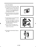
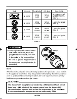
Страница 25: ...urn off the switch es of the electrical appliance s before connecting to the generator c Insert the plug s of the electrical appli ance s into the receptacle Check the amperage of the receptacles used referring to TABLE 1 and be sure not to take a current exceeding the specified amperage Be sure that the total wattage of all appliances dose not exceed the rated output of the generator PILOT LAMP O...

Страница 26: ...e connected electrical device Is grounded WARNING TWIST The duplex 120V receptacle is protected by a GFCI Ground Fault Circuit Interrupter GFCI shuts off the output current from the duplex 120V receptacle when a ground fault occurs in the generator or the appliance Please note that other receptacles are not protected by GFCI CAUTION up to 30A up to 20A up to 20A NEMA 5 20R NEMA L14 20R NEMA L5 30R...

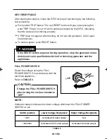
Страница 27: ...e outlets protected by the GFCI indicating that the device is functioning properly If TRIP dose not appear when testing do not use the generator Call a quali fied electrician To restore power push RESET button If the RESET button pops out during operation stop the generator imme diately and call a qualified electrician for checking generator and the appliances WARNING NOTE Voltmeter always indicat...

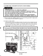
Страница 28: ...to a house wiring generator output power must be taken from the 240V 4P receptacle b Install a transfer switch A transfer switch must be installed to transfer the load from the commercial power source to the generator This switch is necessary to prevent accidents caused by the recovery from power outage Use a transfer switch of the correct capacity Install transfer switch between the meter and the...

Страница 29: ... Operating the generator Set the full power switch to 120V 240V side Turn the house AC breaker off before starting the generator Start the generator and warm it up Turn the house AC breaker on Do not start the generator with electrical appliance s connected and with their switches on Otherwise the appliance s may be damaged by the surge voltage at starting CAUTION ...

Страница 30: ...en gas is discharged through vent holes in the battery dur ing the charging process Do not allow spark or open flame around the genera tor or battery during the charging process Electrolyte fluid can burn eyes and clothing Be extremely careful to avoid con tact If injured wash the affected area immediately with large quantities of water and consult a doctor for treatment When charging a large capa...

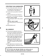
Страница 31: ...e fuel cock OIL SENSOR a The oil sensor detects the fall in oil level in the crankcase and automatic cally stops the engine when the oil level falls below a predetermined level b When engine has stopped automati cally switch off generator s no fuse breaker and check the oil level Refill engine oil to the upper level as instructed on page 6 and restart the engine c If the engine does not start by u...

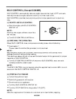
Страница 32: ...DLE CONTROL Turn IDLE CONTROL SWITCH off when the IDLE CONTROL does not work normally under the rated output NOTE The IDLE CONTROL may not operate when the applied load is under 40W In such cases turn the IDLE CONTROL SWITCH off 3 STOPPING THE ENGINE Turn off the switch of load Switch off generator s AC breaker Disconnect tool or appliance Turn the IDLE CONTROL SWITCH off Turn the STOP SWITCH to t...

Страница 33: ...or the appliance will require only 50 to 30 of the wattage to continue running Most electrical tools require 1 2 to 3 times their wattage for running under load during use For example a 5 000 watt generator can power a 1800 to 4000 watt electrical tool Loads such as submersible pumps and air compressors require a very large force to start They need 3 to 5 times the normal running wattage in order ...

Страница 34: ... below Chart lists the minimum wire gauge size for the proper extension cord EXTENSION CORD CHART Use the right extension cord An extension cord should have a suitable wire size for the overall cord length and tool amperage rating This is to prevent a serious voltage drop power loss and possible motor damage Generally heavier gauge wire is required as cord length increases Use the recommendations ...

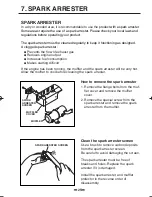
Страница 35: ...and the spark arrester will be very hot Allow the muffler to cool before cleaning the spark arrester How to remove the spark arrester 1 Remove the flange bolts from the muf fler cover and remove the muffler cover 2 Remove the special screw from the spark arrester and remove the spark arrester from the muffler SPARK ARRESTER SCREEN MUFFLER MUFFLER COVER Clean the spark arrester screen Use a brush t...

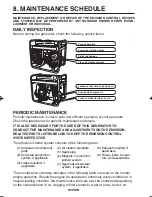
Страница 36: ...ission control system consists of the following parts The maintenance schedule indicated in the following table is based on the normal engine operation Should the engine be operated in extremely dusty condition or in heavier loading condition the maintenance intervals must be shortened depending on the contamination of oil clogging of filter elements wear of parts and so on 1 Carburetor and intern...

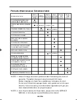
Страница 37: ...rest Makita service dealer Periodic Maintenance Schedule table Maintenance Items Every 8 hours Daily Every 20 hours Every 50 hours Weekly Every 200 hours Monthly Every 500 hours Every 1000 hours CLEAN GENERATOR AND CHECK BOLT AND NUTS Daily CHECK AND REFILL ENGINE OIL CHANGE ENGINE OIL Note1 Initial CLEAN SPARK PLUG CLEAN AIR CLEANER REPLACE AIR CLEANER ELEMENT CLEAN FUEL STRAINER REMOVE CARBON FR...

Страница 38: ...sufficient the engine damage will result and its life will be greatly shortened CLEANING AIR CLEANER Model G2800R Maintaining an air cleaner in proper condi tion is very important Dirt induced through improperly installed improperly serviced or inadequate ele ments damages and wears out engines Always keep the air cleaner element clean a Unhook the cover and remove the cleaner element b Inner elem...

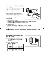
Страница 39: ...hen operating in dusty environments Do not wash elements with kerosene gasoline or oil CAUTION A dirty air cleaner element will cause starting difficulty power loss engine mal functions and shorten engine life extremely Always keep the air cleaner element clean Model G4100R G4101R G6100R G6101R CLEANING AND ADJUSTING SPARK PLUG a If the plug is contaminated with car bon remove it using a plug clea...

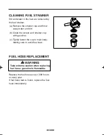
Страница 40: ...d dirt b Clean the screen and strainer cup with gasoline c Tightly fasten the cup to main body making sure to avoid fuel leak FUEL HOSE REPLACEMENT Replace the fuel hose every 1 000 hours or every year If fuel hose leak is found replace the fuel hose immediately WARNING Take extreme caution when replacing fuel hose gasoline is flammable ...

Страница 41: ... eventually deteriorate making engine starting difficult Remove the carburetor float chamber and also drain the carburetor Change engine oil Check for loose bolts and screws tighten them if necessary Clean generator thoroughly with oiled cloth Spray with preservative if avail able NEVER USE WATER TO CLEAN GENERATOR Pull starter handle until resistance is felt leaving handle in that position Store ...

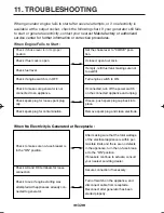
Страница 42: ...ever to CLOSE posi tion If closed open fuel cock If empty refill fuel tank making sure not to overfill If connected turn off the power switch on the connected appliance and unplug If loose push spark plug cap back into place Remove spark plug and clean electrode Turn engine switch to ON Check to make sure no fuse breaker is in the ON position Check AC and DC terminals for loose connection Check to...

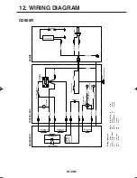
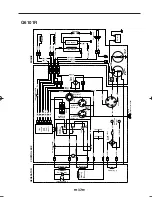
Страница 43: ...ceptacle 120V Condenser Engine switch 1 25Blk DC output terminal 1 25Brn W 1 25Or Circuit breaker Diode stack Assy 2 0Grn 2 0Grn Earth Ground terminal 0 75Grn Y 0 75Grn Y 0 75Blk Oil sensor 0 75Blk Ignition coil Spark plug GRNERATOR CONTROL BOX ENGINE DC Winding W Wiring color cord Blk Black Brn W Brown White R Red Blk W Black White Grn Green W White Blu Blue Grn W Green White Y Yellow LBlu Light ...

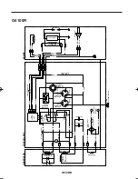
Страница 44: ...inal Circuit breaker Diode stack Assy Earth Ground terminal Full power switch Idle control unit AC output receptacle 120V AC output receptacle 120 240V Idle control switch ENGINE 0 75W 0 75W Solenoid 0 75Blu Charge coil Ignition coil Spark plug Engin switch 1 25Y Condenser 1 25Brn 1 5 3 4 2 1 5 3 4 2 0 75W 0 75W 0 75Blu 0 75LBlu AC output receptacle 120V REC2 W 2 0Grn 0 75Blk 0 75W 0 75W 0 75Grn Y...

Страница 45: ...enser 2 0W 1 25Or 1 25Brn W DC output terminal Circuit breaker Diode stack Assy Full power switch 120 240V Idle control unit AC output receptacle 120V AC output receptacle 120 240V Idle control switch ENGINE 0 75W 0 75W Solenoid 0 75Blu Oil sensor Charge coil Ignition coil Spark plug 1 25Y Condenser 1 25Brn 1 5 3 4 2 1 5 3 4 2 0 75W 0 75W 0 75Blu 0 75LBlu AC output receptacle 120V REC2 W 2 0Grn 0 ...

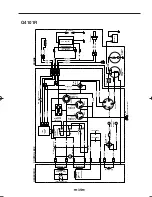
Страница 46: ...1 25Brn Condenser Condenser 2 0W 1 25Or 1 25Brn W DC output terminal Circuit breaker Diode stack Assy Earth Ground terminal Full power switch 120 240V Idle control unit and Fuel cut unit AC output receptacle 120V AC output receptacle 120 240V AC output receptacle 120V No fuse breaker Idle control switch 0 75Blk ENGINE 0 75W 0 75W 0 75W 0 75W Solenoid 0 75Blu 0 75Blu Fuel cut solenoid 0 75Grn W 0 7...

Страница 47: ...uit breaker Diode stack Assy Earth Ground terminal 1 25Grn 1 25R 1 25Or 1 25Gry ST B M M IG Key switch Full power switch 120 240V Idle control unit and Fuel cut unit AC output receptacle 120 240V AC output receptacle 120V AC output receptacle 120V Idle control switch 0 75Blk Diode stack Assy ENGINE 0 75Blk 0 75Blk W Oil sensor 0 75Grn Y 0 75Y 0 75Blk W 0 75Grn W Spark plug Battery Magnetiec switch...

Страница 48: ...13 OPTIONAL PARTS 38 HOW TO INSTALL BATTERY ...

Страница 49: ...PRINTED IN JAPAN November 2004 CE SK Makita Corporation 3 11 8 Sumiyoshi cho Anjo Aichi 446 8502 Japan ...

Отзывы: