15 ENGLISH
NOTE:
To dismount the cutter blades, refer to the
section for dismounting the cutter blade.
Resharpening the cutter blades
CAUTION:
Always wear gloves when
resharpening the cutter blades.
NOTICE:
When resharpening the cutter blades,
sharpen both the upper and lower blade.
NOTICE:
If the cutter blades have considerably
deformed by filing, replace them with new ones.
NOTICE:
As a rough guide, sharpen the cutter
blades every 8 hours of use. Earlier resharpen-
ing is recommended if you often cut the weeds
together with their roots or cut the weeds on a
stony surface or a surface with a lot of obstacles.
Using dull cutter blades result in poor cutting perfor-
mance and damage to the machine.
NOTICE:
Use a diamond file for sharpening
cutter blades.
You can use a disc grinder instead.
1.
Dismount the cutter blades from the attachment.
NOTE:
Refer to the section for dismounting the cutter
blade for detail.
2.
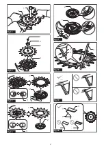
Sharpen the tips and cutting edges of both upper
and lower blades at the angle of 40° using a file.
►
Fig.18:
1.
Cutting edge
2.
Tip
3.
Rib
4.
File
NOTE:
The upper blade should be replaced when the
teeth have been worn to the rib.
3.
Round the root of each blade as illustrated using
the file.
►
Fig.19
NOTICE:
Do not make the root of the blade
angled or chipped.
Doing so result in a crack in the
cutting blade.
Replacing the cutter blades
Optional accessory
CAUTION:
Always wear gloves when replac-
ing the cutter blades.
Before starting, make sure the direction of the upper
and lower blades; the cutting edges (angled surfaces)
on both upper and lower blade face outward each other
when assembled.
►
Fig.20:
1.
Cutting edge
2.
Lower blade
3.
Upper
blade
NOTICE:
If the cutting edges faces same side
or inward each other, you will not able to cut
grass.
Install the cutting blades by the following procedure:
1.
Dismount the old cutter blades from the
attachment.
NOTE:
Refer to the section for dismounting the cutter
blade for detail.
2.
Install a new upper blade onto the holder.
The upper blade has projection on one side. Be sure to
place the upper blade so that the projected side (arrow
marking printed) faces to the gear case.
►
Fig.21:
1.
Upper blade
2.
Gear case
3.
Projection
Align the oval holes in the upper blade with the pins.
Rotate the upper blade clockwise while pushing it down
until the pins hold the upper blade.
►
Fig.22:
1.
Upper blade
2.
Holder (for upper blade)
3.
Pin
NOTICE:
Be sure to position the upper blade so
that all pins hold the upper blade.
3.
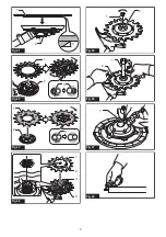
Install a new lower blade onto the holder.
Place the lower blade so that the side with arrow mark-
ing faces to the holder and align the oval holes in the
blade with the pins. After that, rotate the lower blade
clockwise until the pins hold the lower blade.
►
Fig.23:
1.
Lower blade
2.
Holder (for lower blade)
3.
Pin
NOTICE:
Be sure to position the lower blade so
that all pins hold the lower blade.
4.
Put the lower blade (with the holder) onto the
upper blade while aligning the spline of the spindle with
that of the holder.
►
Fig.24:
1.
Lower blade
2.
Holder (for lower blade)
3.
Spindle
4.
Upper blade
5.
Place the clamp washer onto the holder while
aligning the spline of the spindle with that of the clamp
washer. After that, tighten the bolt by hand temporarily.
►
Fig.25:
1.
Bolt
2.
Clamp washer
6.
Align the holes in the lower and upper blades
and insert the hex wrench. After that, securely tighten
the bolt using the box wrench while the hex wrench is
inserted in the hole.
►
Fig.26:
1.
Box wrench
2.
Hex wrench
NOTE:
Refer to the section for dismounting the cutter
blades for how to align the holes of upper and lower
blades.
7.
Remove the hex wrench and then put the blade
cover onto the cutting blades.
Lubricating moving parts
NOTICE:
Follow the instruction of the fre-
quency and amount of grease supplied.
Otherwise
insufficient lubrication may damage moving parts.
Gear case:
CAUTION:
Do not apply grease when the
gear case is hot.
Hot gear case can cause burn
injury.
Remove the gear case access bolt using the box
wrench.
Apply grease (Shell Alvania 2 or equivalent) to the gear
case through the grease hole every around 50 working
hours.
►
Fig.27:
1.
Grease hole
Содержание EM407MP
Страница 2: ...11 1 Fig 1 12 1 2 3 4 11 10 9 8 Fig 2 1 2 3 5 6 7 8 9 10 11 12 13 14 4 Fig 3 1 2 Fig 4 1 Fig 5 2 ...
Страница 3: ...1 2 3 Fig 6 1 Fig 7 Fig 12 3 1 2 Fig 8 Fig 9 1 2 Fig 10 1 1 2 2 3 4 Fig 11 1 2 3 Fig 12 3 ...
Страница 5: ...1 2 3 Fig 21 1 2 3 Fig 22 1 2 3 Fig 23 1 2 4 3 Fig 24 2 1 Fig 25 1 2 Fig 26 1 Fig 27 Fig 28 5 ...
Страница 6: ...1 Fig 29 Fig 30 6 ...
Страница 17: ...139 ...

