background image

8 ENGLISH

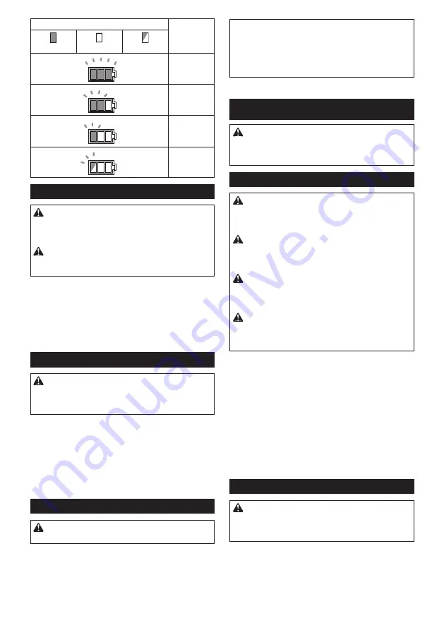
Battery indicator status

Remaining 

battery 

capacity

On

Off

Blinking

50% to 100%

20% to 50%

0% to 20%

Charge the 

battery

Trigger-lock button

CAUTION:


Before installing the battery car-

tridge into the tool, always check to see that the 

switch trigger actuates properly and returns to 

the "OFF" position when released.

CAUTION:


When not operating the tool, 

depress the trigger-lock button from B side to 

lock the switch trigger in the OFF position.

► 

Fig.4:


1.

 Trigger-lock button 

2.

 Switch trigger

► 

Fig.5

To prevent the switch trigger from accidentally pulled, 

the trigger-lock button is provided. 


To pull the switch trigger, depress the trigger-lock button 

from A side. 


After use, always press in the trigger-lock button from B side.

Adjusting the depth of pin-nailing

WARNING:


Always make sure that your 

fingers are not placed on the switch trigger or 

the contact element and the battery cartridge is 

removed before adjusting the depth of nailing.

Depth of pin-nailing can be adjusted on this pin nailer. To 

adjust the depth of nailing, turn the adjuster. The depth 

of nailing is the deepest when the adjuster is turned fully 

in the A direction shown in the figure. It will become shal-

lower as the adjuster is turned in the B direction. Depth 

can be adjusted 1.5 mm to the maximum.

► 

Fig.6:


1.

 Adjuster

► 

Fig.7:


1.

 Too deep 

2.

 Flush 

3.

 Too shallow

Lighting up the lamp

CAUTION:


Do not look in the light or see the 

source of light directly.

Pull the switch trigger or actuate the contact element to 

light up the lamp. The lamp keeps on lighting while pull-

ing the switch trigger or actuating the contact element. 

The lamp goes out approximately 10 seconds after 

releasing the switch trigger and the contact element.

► 

Fig.8:


1.

 Lamp

NOTE:

 Use a dry cloth to wipe the dirt off the lens of 

the lamp. Be careful not to scratch the lens of lamp, or 

it may lower the illumination.

NOTE:

 Even in the lamp lights up when the battery 

power residual gets small, pin nailer may not fire pin 

nails. In this case, charge the battery cartridge.

ASSEMBLY

CAUTION:


Always make sure that your fingers 

are not placed on the switch trigger or the con-

tact element and the battery cartridge is removed 

before carrying out any work on the pin nailer.

Loading the pin nailer

CAUTION:


Always make sure that the battery 

cartridge is removed before loading the pin nailer.


Unintentional firing may cause personal injuries and 

property damage.

CAUTION:


Do not abruptly slide the magazine 

of the pin nailer loaded with pin nails.

 Accidentally 

dropping pin nails especially when working in high 

places may cause personal injuries.

CAUTION:


Load pin nails in the correct direc-

tion.

 Loading in wrong direction may cause prema

-

ture wear and tear of the driver and damage of the 

other parts.

CAUTION:


Do not use deformed connected 

pin nails.

 Use pin nails specified in this manual. 

Using pin nails other than those specified may cause 

pin nail jamming and breakage of the pin nailer.

1.

  Remove the battery cartridge.

2.


Press the locking lever and slide the magazine backward.

3.

  Align the tip of pin nails with the grooves at the 

bottom of the magazine and push the whole part of pin 

nails toward the driver guide. (Be careful to place pin 

nails in the right direction.)

► 

Fig.9:


1.

 Pin nails 

2.

 Magazine 

3.

 Locking lever 

4.

 Driver guide

4.

  After loading pin nails, push back the magazine in 

place until it clicks.

To remove pin nails, follow the installation procedures 

in reverse.

Nose adapter

CAUTION:


Always make sure that your 

fingers are not placed on the switch trigger or 

the contact element and the battery cartridge is 

removed before installing the nose adapter.

When firing pin nails on the material with easily-marred sur-

faces, use the nose adapter. To install the nose adapter, place 

it over the driver guide cover so that the protrusion inside the 

nose adapter fits to the dent in the driver guide cover.

You can store the nose adapter on the holder on the 

back end of the magazine to keep it from being lost.

Содержание DPT353Y1J

Страница 1: ...rice per chiodi a spillo a batteria ISTRUZIONI PER L USO 24 NL Accunagelpistool GEBRUIKSAANWIJZING 30 ES Clavadora Inalámbrica MANUAL DE INSTRUCCIONES 36 PT Pinador a Bateria MANUAL DE INSTRUÇÕES 43 DA Akku stiftepistol BRUGSANVISNING 49 EL Φορητό καρφωτικό βελονιών ΕΓΧΕΙΡΙΔΙΟ ΟΔΗΓΙΩΝ 55 TR Akülü Başsız Çivi Çakma Tabancası KULLANMA KILAVUZU 62 ...

Страница 2: ...1 2 3 Fig 1 1 2 Fig 2 1 Fig 3 1 2 Fig 4 A B Fig 5 A B 1 Fig 6 2 1 3 Fig 7 1 Fig 8 2 ...

Страница 3: ...3 2 4 1 Fig 9 4 3 1 2 Fig 10 Fig 11 1 2 3 Fig 12 1 Fig 13 4 1 3 2 Fig 14 1 2 Fig 15 3 ...

Страница 4: ...Fig 16 Fig 17 1 2 Fig 18 1 2 3 Fig 19 4 ...

Страница 5: ...tions of use taking account of all parts of the operating cycle such as the times when the tool is switched off and when it is running idle in addition to the trigger time EC Declaration of Conformity For European countries only The EC declaration of conformity is included as Annex A to this instruction manual SAFETY WARNINGS General power tool safety warnings WARNING Read all safety warnings inst...

Страница 6: ...ilure to follow the safety rules stated in this instruction manual may cause serious personal injury Important safety instructions for battery cartridge 1 Before using battery cartridge read all instruc tions and cautionary markings on 1 battery charger 2 battery and 3 product using battery 2 Do not disassemble battery cartridge 3 If operating time has become excessively shorter stop operating imm...

Страница 7: ...o the motor to extend tool and battery life The tool will auto matically stop during operation if the tool or battery is placed under one of the following conditions Overload protection When the tool battery is operated in a manner that causes it to draw an abnormally high current the tool automatically stops without any indication In this sit uation turn the tool off and stop the application that...

Страница 8: ...p lights up when the battery power residual gets small pin nailer may not fire pin nails In this case charge the battery cartridge ASSEMBLY CAUTION Always make sure that your fingers are not placed on the switch trigger or the con tact element and the battery cartridge is removed before carrying out any work on the pin nailer Loading the pin nailer CAUTION Always make sure that the battery cartrid...

Страница 9: ...bove Fig 15 1 Switch trigger 2 Contact element You can also drive the pin nails when dragging the tool to the next area with the contact element pressed against the material and pulling the switch trigger Fig 16 If the head of the pin nail remains above the workpiece surface drive the pin nail while holding the pin nailer head firmly against the workpiece Fig 17 NOTE If the head of the pin nail st...

Страница 10: ...e Centers always using Makita replacement parts OPTIONAL ACCESSORIES CAUTION These accessories or attachments are recommended for use with your Makita tool specified in this manual The use of any other accessories or attachments might present a risk of injury to persons Only use accessory or attachment for its stated purpose If you need any assistance for more details regard ing these accessories ...

Страница 11: ... de l usage réel de l outil électrique peut être différente de la valeur d émission déclarée suivant la façon dont l outil est utilisé AVERTISSEMENT Les mesures de sécurité à prendre pour protéger l utilisateur doivent être basées sur une estimation de l exposition dans des condi tions réelles d utilisation en tenant compte de toutes les composantes du cycle d utilisation comme par exemple le mome...

Страница 12: ...la sécurité lors du transport par exemple sur des véhicules ou des wagons 14 Vérifiez soigneusement le mur plafond plan cher toit ou autre structure pour éviter les risques d électrocution de fuite de gaz d ex plosion etc en agrafant des fils dénudés des conduites ou des tuyaux de gaz 15 Utilisez exclusivement les éléments de fixation spécifiés dans le présent manuel L utilisation d autres élément...

Страница 13: ...gez la batterie si elle est restée inutili sée pendant une période prolongée plus de six mois DESCRIPTION DU FONCTIONNEMENT ATTENTION Assurez vous toujours que l outil est hors tension et que sa batterie est retirée avant de l ajuster ou de vérifier son fonctionnement Insertion ou retrait de la batterie ATTENTION Éteignez toujours l outil avant de mettre en place ou de retirer la batterie ATTENTIO...

Страница 14: ...Avant d insérer la batterie dans l outil vérifiez toujours que la gâchette fonctionne bien et revient en position d arrêt lorsque vous la relâchez ATTENTION Lorsque vous n utilisez pas l outil appuyez sur le côté B du bouton de verrouillage de la gâchette pour verrouiller la gâchette en position d arrêt Fig 4 1 Bouton de verrouillage de la gâchette 2 Gâchette Fig 5 Pour éviter tout déclenchement a...

Страница 15: ...age 4 Guide d entraînement 4 Après avoir chargé les clous sans tête remettez le magasin en place en le poussant jusqu au clic Pour retirer les clous sans tête inversez les étapes de la procédure d installation Adaptateur de bec ATTENTION Vérifiez toujours que vos doigts ne se trouvent pas sur la gâchette ou sur l élément de contact et que la batterie a été retirée avant d installer l adaptateur de...

Страница 16: ...us les clous restants de la bande précédente sur un matériau destiné au rebut Vérification de la quantité de clous restants Vous pouvez vérifier la quantité de clous sans tête restants grâce à la fenêtre de contrôle Le témoin rouge se déplace vers l orifice de projection à mesure que le nombre de clous sans tête restants diminue Fig 18 1 Fenêtre de contrôle 2 Témoin Retrait des clous sans tête coi...

Страница 17: ...wendet werden WARNUNG Die Schwingungsemission während der tatsächlichen Benutzung des Elektrowerkzeugs kann je nach der Benutzungsweise des Werkzeugs vom angegebenen Emissionswert abweichen WARNUNG Identifizieren Sie Sicherheitsmaßnahmen zum Schutz des Benutzers anhand einer Schätzung des Gefährdungsgrads unter den tatsächlichen Benutzungsbedingungen unter Berücksichtigung aller Phasen des Arbeits...

Страница 18: ...rzeugen und Wagen 14 Überprüfen Sie Wände Decken Fußböden Dach und dergleichen sorgfältig um durch Kontakt mit Strom führenden Kabeln Isolierrohren oder Gasrohren verursachte mögliche elektrische Schläge Gaslecks Explosionen usw zu vermeiden 15 Verwenden Sie nur die in dieser Anleitung ange gebenen Befestigungselemente Die Verwendung anderer Befestigungselemente kann eine Funktionsstörung des Werk...

Страница 19: ...tur zwischen 10 40 C Lassen Sie einen heißen Akku abkühlen bevor Sie ihn laden 4 Der Akku muss geladen werden wenn er lange Zeit länger als sechs Monate nicht benutzt wird FUNKTIONSBESCHREIBUNG VORSICHT Vergewissern Sie sich vor der Durchführung von Einstellungen oder Funktionsprüfungen des Werkzeugs stets dass das Werkzeug ausgeschaltet und der Akku abge nommen ist Anbringen und Abnehmen des Akku...

Страница 20: ...ät Ein Aus Blinkend 50 bis 100 20 bis 50 0 bis 20 Akku aufladen Auslösersperrknopf VORSICHT Vergewissern Sie sich vor dem Einsetzen des Akkus in das Werkzeug stets dass der Ein Aus Schalter ordnungsgemäß funktio niert und beim Loslassen in die AUS Stellung zurückkehrt VORSICHT Wenn Sie das Werkzeug nicht benutzen drücken Sie den Auslösersperrknopf auf der Seite B hinein um den Auslöser in der Stel...

Страница 21: ...2 Drücken Sie den Feststellhebel und schieben Sie das Magazin nach hinten 3 Richten Sie die Spitzen der Stiftnägel auf die Nuten am Boden des Magazins aus und schieben Sie den ganzen Teil der Stiftnägel in Richtung der Treiberführung Platzieren Sie die Stiftnägel in der korrekten Richtung Abb 9 1 Stiftnägel 2 Magazin 3 Feststellhebel 4 Treiberführung 4 Schieben Sie das Magazin nach dem Laden der S...

Страница 22: ...as Werkstück gedrückt Abb 17 HINWEIS Wenn der Kopf des Stiftnagels noch immer oberhalb der Werkstückoberfläche bleibt obwohl Sie den Pintackerkopf gedrückt halten ist das Material möglicherweise nicht für den Pintacker geeignet Fortgesetzter Gebrauch des Pintackers auf solchem Material kann zu einer Beschädigung des Pintackertreibers und oder Klemmen des Pintackers führen Leerschuss Sicherungsmech...

Страница 23: ... unter ausschließlicher Verwendung von Makita Originalersatzteilen ausgeführt werden SONDERZUBEHÖR VORSICHT Die folgenden Zubehörteile oder Vorrichtungen werden für den Einsatz mit dem in dieser Anleitung beschriebenen Makita Werkzeug empfohlen Die Verwendung anderer Zubehörteile oder Vorrichtungen kann eine Verletzungsgefahr darstellen Verwenden Sie Zubehörteile oder Vorrichtungen nur für ihren v...

Страница 24: ...www makita com Makita Europe N V Makita Corporation 3 11 8 Sumiyoshi cho Anjo Aichi 446 8502 Japan Jan Baptist Vinkstraat 2 3070 Kortenberg Belgium 885545 994 EN FR DE IT NL ES PT DA EL TR 20161011 ...

Отзывы: