background image

20 ENGLISH

Deflating plastic inflatables

Optional accessory

NOTICE:


An exhaust air stream flows through 

the blower outlet of the tool. Do not vent exhaust 

air into a wall, ceiling, or concealed space of 

building.

NOTICE:


Avoid deflating inflatable items in wet 

and dusty conditions since water, dust, and sim-

ilar external substances on surfaces may reach 

into the motor causing damages to the tool. Dry 

and clean inflatables off thoroughly before per

-

forming deflating operation.

NOTICE:


Never leave the tool unattended while 

deflating inflatables. Running the motor contin

-

uously after deflation is completed may cause 

overheating.

Recommended nozzles and attachments

— 

Air vent hose complete

— 

Pinch valve nozzle

— 

Rubber attachment 

20 - 30

— 

Rubber attachment 

65

Deflate inflatable items with proper nozzles according to 

your preferences and applications.

1.

  Place a nozzle or rubber attachment onto the air 

vent hose complete.

2.

  Replace the dust cap on the suction inlet of the 

tool with the air vent hose complete.

3.

  Insert the nozzle into the air valve or place the 

attachment over the air valve on inflatable items, and 

pull the switch trigger to start deflating.

4.

  Slowly release the switch trigger to reduce suc-

tion volume as an inflatable item comes close to fully 

deflated.

5.

  Remove the nozzle or attachment from the air 

valve after stopping the air flow and then close the air 

valve.

With pinch valve nozzle

Fig.38

With rubber attachment 20 - 30

Fig.39

With rubber attachment 65

Fig.40

MAINTENANCE

CAUTION:


Always be sure that the tool is 

switched off and the battery cartridge is removed 

before attempting to perform inspection or 

maintenance.

To maintain product SAFETY and RELIABILITY, 

repairs, any other maintenance or adjustment should 

be performed by Makita Authorized or Factory Service 

Centers, always using Makita replacement parts.

NOTICE:


Never use gasoline, benzine, thinner, 

alcohol or the like. Discoloration, deformation or 

cracks may result.

Cleaning

Cleaning body

Clean the body of your tool with a dry cloth or cloth 

dampened in soapy water at regular intervals.

Cleaning nozzles

Clear clogs or dust that block the openings of nozzles 

before and after each use.

Содержание DAS180Z

Страница 1: ...INSTRUCTION MANUAL Cordless Dust Blower DAS180 ENGLISH Original instructions Read before use ...

Страница 2: ...arch and development the specifications herein are subject to change without notice Specifications may differ from country to country The weight may differ depending on the attachment s including the battery cartridge The lightest and heavi est combinations according to EPTA Procedure 01 2014 are shown in the table Applicable battery cartridge and charger Battery cartridge BL1815N BL1820B BL1830B ...

Страница 3: ...e tool Using as inflator Inflating large inflatable pools or air mattresses Using as deflator Deflating large inflatable pools or air mattresses Functioning as a joint between air vent hose complete and rubber attachments ø13 mm Wide range nozzle Blowing air over dirt and liquid on desktop and wide open area Blowing range 120 with 5 holes ø6 0 mm As a single hole diameter Pinch valve nozzle Inflat...

Страница 4: ...ith appropriate nozzles in operation Rubber attachment 20 30 Nozzle head suitable for deflating air mattress raft boat and pool This attachment requires to be installed with the air vent hose complete and nozzle 13 together ø20 30 mm Measured as outer diameter Rubber attachment 65 Attachment suitable for packaging your clothes by compressing air out of them This attachment requires to be installed...

Страница 5: ...ar protection WARNING The noise emission during actual use of the power tool can differ from the declared value s depending on the ways in which the tool is used especially what kind of workpiece is processed WARNING Be sure to identify safety measures to protect the operator that are based on an estima tion of exposure in the actual conditions of use tak ing account of all parts of the operating ...

Страница 6: ... Carrying power tools with your finger on the switch or energising power tools that have the switch on invites accidents 4 Remove any adjusting key or wrench before turning the power tool on A wrench or a key left attached to a rotating part of the power tool may result in personal injury 5 Do not overreach Keep proper footing and balance at all times This enables better control of the power tool ...

Страница 7: ...person using only identical replacement parts This will ensure that the safety of the power tool is maintained 2 Never service damaged battery packs Service of battery packs should only be performed by the manufacturer or authorized service providers 3 Follow instruction for lubricating and chang ing accessories Cordless Dust Blower Safety Instructions Training 1 Read the instructions carefully Be...

Страница 8: ...ure using a reliable and calibrated measuring equipment 8 Never leave the tool unattended when the nozzle or attachment is attached to the object or during operation 9 Do not use the tool as a vacuum cleaner Performing dust collection may damage the tool 10 Do not use the tool as a breathing device 11 Use only standard accessories provided by Makita The use of any other accessories or attach ments...

Страница 9: ...not touch the terminal of the tool imme diately after use as it may get hot enough to cause burns 16 Do not allow chips dust or soil stuck into the terminals holes and grooves of the battery cartridge It may cause heating catching fire burst and malfunction of the tool or battery car tridge resulting in burns or personal injury 17 Unless the tool supports the use near high voltage electrical power...

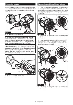
Страница 10: ...or housing while removing the nozzle The lock sleeve slides back towards the motor housing when the nozzle is released from the lock 1 2 Fig 3 1 Lock sleeve 2 Motor housing Removing and installing dust cap 1 Turn the dust cap on the suction inlet at the rear of the housing counterclockwise to take the dust cap out of the housing Two locking tabs on the dust cap can be disengaged by aligning them w...

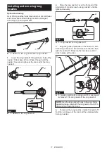
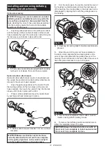
Страница 11: ... over the front end of the long nozzle R Hand screw the long nozzle F until it is tightened securely 1 2 Fig 8 1 Long nozzle F 2 Long nozzle R 3 Align the guide projections on the nozzle 13 with the locking notches on the lock sleeve of the tool then push the nozzle 13 firmly into the lock sleeve until it locks in place with a click 1 2 3 4 5 6 Fig 9 1 Guide projection 2 Locking notch 3 Lock sleev...

Страница 12: ...ks in place with a click ii Place a rubber attachment over the nozzle head by pushing and hand screwing it in place 1 1 2 3 Fig 11 1 Rubber attachments 2 Nozzle 13 3 Air vent hose complete NOTICE Make sure that the nozzle has been correctly attached to the air vent hose complete so the guide projections on the nozzle neatly fit into the locking notches on the lock sleeve 2 Turn the dust cap on the...

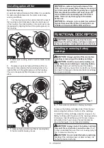
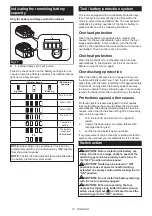
Страница 13: ...ardly Be sure to shake or blow dust off the filter with care FUNCTIONAL DESCRIPTION CAUTION Always be sure that the tool is switched off and the battery cartridge is removed before adjusting or checking function on the tool Installing or removing battery cartridge CAUTION Always switch off the tool before installing or removing of the battery cartridge CAUTION Hold the tool and the battery car tri...

Страница 14: ...on let the tool cool down before turning the tool on again Overdischarge protection When the battery becomes low on power during use the lamp will blink to alert you Then the tool automati cally stops with the lamp remaining lit for approximately 10 seconds shortly after the battery power becomes too low to operate during continuing use In such cases remove the battery from the tool and charge the...

Страница 15: ...reasing pressure on the switch trigger Release the switch trigger to stop 1 Fig 19 1 Switch trigger Lock button For continuous operation push in the lock button while pulling the switch trigger and then release the switch trigger To cancel the locked on operation pull the switch trigger fully then release it 1 2 Fig 20 1 Switch trigger 2 Lock button Adjusting air volume Air volume can be changed i...

Страница 16: ...nding load rated for your tools racks and holders needs to be learned beforehand Do not place the tool if it exceeds the withstanding load on the racks and holders CAUTION Be sure that the hanging hole is securely hooked before releasing your hold Use the hanging hole at the top rear of the housing to hang the tool on a hook of racks and holders 1 2 Fig 23 1 Hanging hole 2 Hook Installing hook Opt...

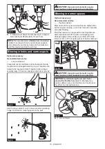
Страница 17: ...les Nozzle 3 Blow into confined spots corners and spaces by the walls to dust off Point the nozzle straight at spaces at a reasonable distance and squeeze the switch trigger to control blowing air volume Fig 26 Fig 27 CAUTION Keep the nozzle away a reasonable distance from blowing spots to avoid blowing up dust into the air CAUTION Use personal protective equip ment such as a dust mask and eye pro...

Страница 18: ...bles with pinch valve nozzle Inflate garden pools air mattresses and similar large plastic inflatables with nozzle 13 Insert the nozzle into an air inlet on an inflatable item and pull the switch trigger to start inflating Slowly release the switch trigger to reduce air volume as the inflatable item comes close to fully inflated Remove the nozzle from the air inlet after stopping the air flow and ...

Страница 19: ... R only to have a shorter operating range for instance cleaning spots on the wall Fig 35 CAUTION Use personal protective equip ment such as a dust mask and eye protection Blowing in narrow spaces Optional accessory Recommended nozzles Flexible nozzle 6 Blow dust out of any hard to reach spots Highly effec tive for engine cleaning in car dust removal computer case dust blowing Point the nozzle at a...

Страница 20: ...ir vent hose complete 3 Insert the nozzle into the air valve or place the attachment over the air valve on inflatable items and pull the switch trigger to start deflating 4 Slowly release the switch trigger to reduce suc tion volume as an inflatable item comes close to fully deflated 5 Remove the nozzle or attachment from the air valve after stopping the air flow and then close the air valve With ...

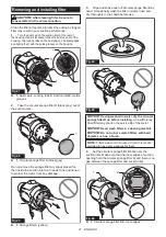
Страница 21: ...nside the suction inlet as it needs to be positioned to protect the motor from any damage 1 Fig 43 1 Sponge filter A yellow 3 Wipe and shake dust off circular sponge filter B by hand Occasionally wash the filter in water rinse and dry thoroughly in the shade before use Fig 44 Fig 45 NOTICE Having washed in water dry the circular sponge filter B up before installing An insufficiently dried filter m...

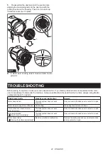
Страница 22: ...lacement parts for repairs State of abnormality Probable cause malfunction Remedy Motor does not run The drive system does not work correctly Ask your local authorized service center for repair Motor stops running after a little use Overheating Stop using the tool to cool it down The tool does not reach the maxi mum air volume The drive system does not work correctly Ask your local authorized serv...

Страница 23: ...its stated purpose If you need any assistance for more details regard ing these accessories ask your local Makita Service Center Nozzle 3 Nozzle 7 Nozzle 13 Wide range nozzle Pinch valve nozzle Flexible nozzle 6 Long nozzles set Air vent hose complete Rubber attachment 20 30 Rubber attachment 65 Filter C Hook Makita genuine battery and charger NOTE Some items in the list may be included in the pro...

Страница 24: ...www makita com Makita Europe N V Makita Corporation 3 11 8 Sumiyoshi cho Anjo Aichi 446 8502 Japan Jan Baptist Vinkstraat 2 3070 Kortenberg Belgium 885A20B225 EN 20221028 ...

Отзывы: