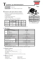


C
ircuit diagram
W
iring diagram
P
6
/
7
White
Blue
Color index of lead wires' sheath
Black
Red
Fig. D-1
Transparent
Put Line filter between
DC motor and Controller.
Refer to
Fig. D-2
.
Yellow
Line filter (if used)
DC motor
Grounding Terminal to be
connected to Motor Housing set.
Refer to
Fig. D-4
.
Grounding Terminal
to be connected to
Drum of DC motor.
Refer to
Fig. 9
.
Terminal
Controller
Switch
unit
Grounding
Lead wire
Fig. D-2
Pass the Controller’s lead wires (black, red)
through Line filter.
Note: 1) Line filter is not used for some countries.
2) Be sure to see
Figs. 6R and 6F
.
DC motor and Line filter
Line filter
(if used)
Controller’s lead
wires (black, red)
Line filter
(if used)
Connect Flag connectors to Terminals of DC motor so that
the wire connecting portions faces the Lead wire holder side.
Lead wire holder of
Motor rubber ring B
Wire connecting portion
on Flag connector
Fig. D-3
Terminal
Wire connecting portion
Flag connector
Terminal
Marks of positive and negative terminals.
Face the wire connecting portions of Flag connectors
to the marks of positive and negative terminals.