


P
5
/
7
R
epair
[3] DISASSEMBLY/ASSEMBLY
[3]-2. DC motor, Controller, Switch unit (cont.)
ASSEMBLING
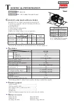
Fig. 8
Fig. 9
(6) Take the disassembling step in reverse to reassemble the removed parts.
Motor rubber ring A is set in place by assembling Motor housing set.
Aligning these protrusions to
the ribs of Motor housing set,
put Motor rubber ring A on
DC Motor in Motor housing set.
Rib
Motor rubber ring A with Ball bearing 6000DDW
As the stepped portion of Motor drum interferes in insertion of
Grounding terminal, bend the grounding terminal in advance.
Motor
drum
Insert Grounding terminal deep into the gap
between Motor rubber ring A and DC Motor.
Make sure that Grounding terminal
is set in place as illustrated below.
Motor rubber
ring A
Grounding terminal
Grounding Terminal
Motor rubber ring A
Motor rubber ring A
Grounding terminal
Grounding terminal
Motor
drum
Motor
drum
less than 3mm
Motor rubber ring A
Lead wire
(transparent)
Flat washer 10
Spindle top protruded from
Ball bearing 6000DDW
Note
: Do not fit Motor rubber ring A to
Motor housing set completely
in this step.
(4) Insert Motor rubber ring A between Motor housing set and DC motor, then pass Flat washer 10 through Spindle.(
Fig. 8
)
Note
: Push down Motor rubber ring A so that Spindle top can protrude from Ball bearing 6000DDW as illustrated in
Fig. 8
.
(5) Set Grounding terminal in place. Refer to
Fig. 9
.
Note
: Regarding the opposite Grounding terminal of Lead wire (transparent), Refer to
Fig. D-4
.