P
6
/
C
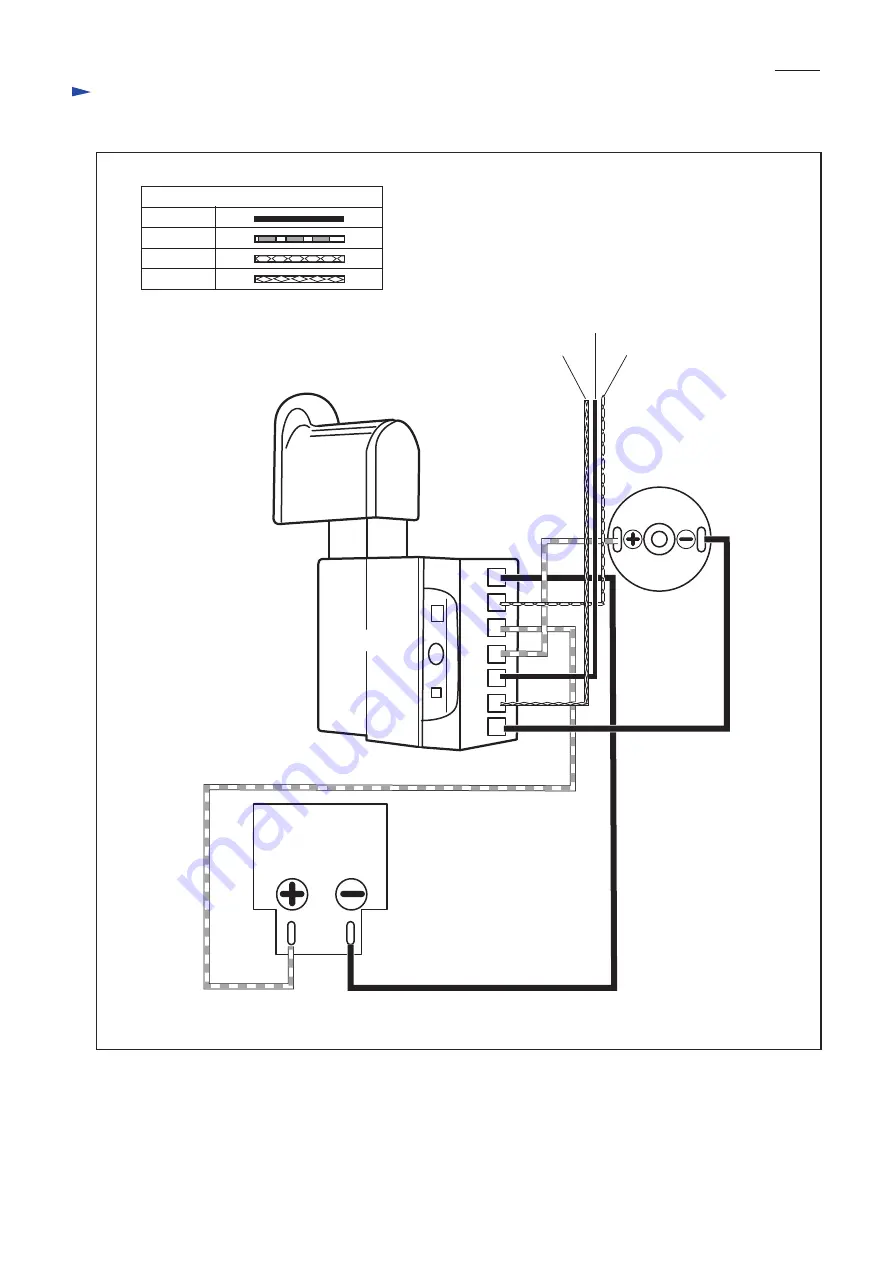
ircuit Diagram
Switch
Battery holder
DC motor
FET gate
FET source
Fig. D-1
FET drain
B-
B+M2
M1
G
SD
Color index of lead wires' sheath
BlackRed
Blue
Yellow
Страница 1: ...ccording to EPTA Procedure 01 2003 6 kg lbs Standard equipment Optional accessories Fast charger DC18RA for USA Canada Guam Panama Colombia Mexico Fast charger DC18RC for all countries except the coun...
Страница 2: ...remove Fan housing L 2 Lock Fan AP 10302 by inserting 1R309 or Phillips screwdriver into the hole of the Fan and remove M5x8 Pan head screw while Holding Fan AP 10302 with gloved hand as drawn above N...
Страница 3: ...ut Motor rubber ring B Motor rubber ring A DC motor It is difficult to pull off Receptacles from DC motor by hand because of their tight connecting In this case remove each Receptacle by levering up w...
Страница 4: ...bber ring B so that its Plus terminal comes to the left side of the groove of Motor rubber ring B 2 Fit Motor rubber ring A to DC motor while aligning its groove to that of Motor rubber ring B 3 Conne...
Страница 5: ...les BUB143 Battery holder BUB183 Solder Connect Lead wires to Battery holder by soldering Note Battery holder of BUB183 is different from that of the other 18V models so that the lead wires are solder...
Страница 6: ...P 6 6 Circuit Diagram Switch Battery holder DC motor FET gate FET source Fig D 1 FET drain B B M2 M1 G S D Color index of lead wires sheath Black Red Blue Yellow...