P 17 / 28
R
epair
[3] DISASSEMBLY/ASSEMBLY
[3] -4. Top cover section
DISASSEMBLING
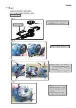
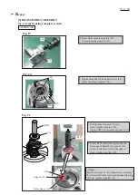
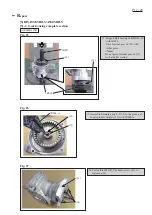
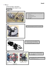
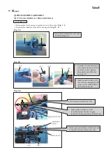
Fig. 42
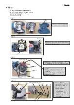
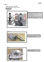
Fig. 44
Fig. 43
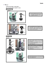
2. Remove Compression spring 5 (4)
with Slotted screwdriver.
<Note>
Set Change knob (2) to Roto-orbit mode.
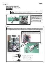
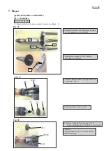
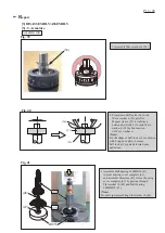
1. Disassemble Gear housing complete section in the order of
Fig. 3
-
8
.
4. Remove O ring 65 (17) from Top cover (7).
5. Remove Spur gear 31 (9) with 1R045
from Top cover (7).
1R045
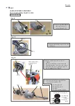
3. Unscrew 4x14 Tapping screw (1).
Change knob (2), Change plate (3)
and Guide plate (5) are removed
from Top cover (7).
(2)
(1)
(7)
(7)
(9)
(17)
(3)
(2)
(5)
(4)
Roto-orbit mode.
Slotted
screwdriver
(9)


