P
5
/ 1
0
R
epair
[3] DISASSEMBLY/ASSEMBLY
[3]-2. Motor section (cont.)
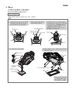
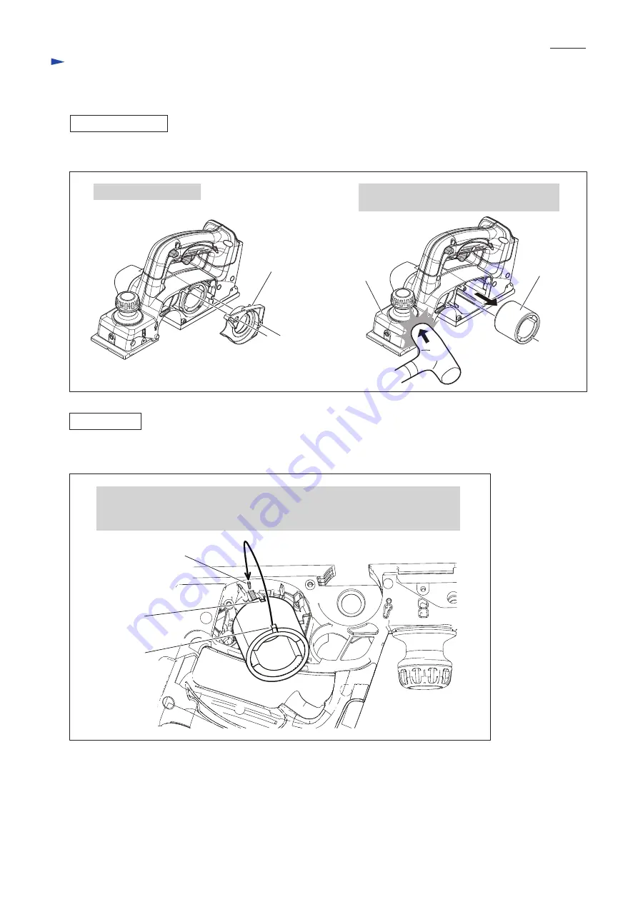
DISASSEMBLING
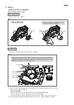
(4) Remove Yoke unit. (
Fig. 7
)
Fig. 7
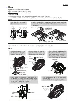
Fig. 8
8. Remove Baffle plate.
9. Remove Yoke unit by tapping Main frame
complete with Plastic hammer.
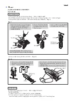
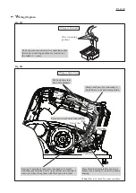
While aligning Notch of Bracket side to Pilot Rib, insert Yoke unit into Mainframe
complete to fit Notch of Commutator side to the accepting Rib which is molded in
Main frame complete on the Commutator side.
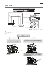
(2) Assemble Armature to Bracket, and set V-pulley 4-24L to Armature by taking the disassembling
step in reverse. (Refer to
Fig. 6
)
Note in Assembling:
1. Tighten V-pulley 4-24L to Armature shaft by turning it
counterclockwise
.
2. It is not necessary to tighten V-pulley 4-24L to very high torque.
Reaction torque caused by stopping the rotation prevents V-pulley 4-24L from being loose.
(3) further assemble by taking the disassembling step in reverse. (Refer to
Figs. 5, 3 and 2
)
ASSEMBLING
Baffle plate
Yoke unit
Notch of
Bracket side
Notch of
Commutator side
Pilot Rib
(1) Assemble Yoke unit to Main frame complete. (
Fig. 8
)
Main frame
complete


