manualshive.com logo in svg
background image

P  6/ 11

R

epair

[3] DISASSEMBLY/ASSEMBLY
[3] -2. Motor Complete, Gear Assembly (cont.)

ASSEMBLING

(1) Assemble Ball bearing 6803LLU to Gear housing. Refer to the drawing on the left in 

Fig. 7

.

(2) Mount Ball bearing 6806LLU to Spur gear 10. Refer to the drawing on the bottom in 

Fig. 6

.

(3) Assemble the Spur gear 10 section to Gear housing. Refer to the drawing on the upper right in 

Fig. 6

.

(4) Mount Oil seal 30 to Spacer. Refer to the drawing on the bottom in 

Fig. 5

.

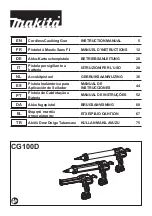
(5) Assemble Plate 23, Spacer, Internal gear 48 and Spur gear 9C complete to Gear housing as drawn in 

Fig. 8

.

Fig. 9

Fig. 8

Plate 23

Oil seal 30

Internal gear 48

Gear housing

Spur gear 9C

complete

Spacer

Note:

 Assemble Spacer with the convex side


of it facing to Internal gear 48.

(6) Assemble the parts on the Flat washer 5 side to Gear housing as drawn in 

Fig. 9

.

1R027

Carrier A complete

Pins of Carrier 

A complete

Spur gear 19B

( 3 pcs.)

Flat washer 5

Carrier B

Pin 3  (9 pcs.)

Gear housing

< Note for Assembling of Pin 3 >

Do not lubricate on Pin 3. 

And, be careful that Pin 3 easily falls off.

Stop ring E-4

Spur gear 9C complete

1. Set Carrier A complete on 1R027, and

    assemble Carrier B and 9 pcs. of Pin 3.

3. Assemble Spur gear 19B to the Pins of Carrier A complete.

    And then, mount Flat washer 5 to Gear housing.

4. Assemble Stop ring E-4 to the shaft

    on Spur gear 9C complete.

2. While holding Internal gear 48

  with your fingers, assemble Gear housing

  to Carrier A complete section.

Содержание BCG140

Страница 1: ...ype model Holder joint for 600ml type model Piston for cartridge Piston for sausage pack Piston for bulk sealant Rubber ring for sausage pack Rubber ring for bulk sealant Nozzle for sausage pack Nozzl...

Страница 2: ...6806LLU when removing Spur gear 10 separating Spur gear 10 from Ball bearing 6806LLU Bearing Setting Pipe 23 15 2 Bearing Setting Pipe 28 20 2 Fig 1 Item No Description Amount Portion to lubricate Spu...

Страница 3: ...complete 1 Disassemble Holder complete by turning counterclockwise 2 Disassemble Piston complete by unscrewing M3x18 Pan head screw Plate Housing R complete Housing L complete M5x16 Pan head screw 4...

Страница 4: ...sening three 3x16 Tapping screws Stop ring E 4 Flat washer 5 Flat washer 5 Gear housing Flat washer 12 Internal gear 48 Spur gear 19A 6 pcs Spur gear 9B complete Spur gear 19B 3 pcs Flat washer 5 Spur...

Страница 5: ...6LLU removed in Fig 6 1 Set 1R029 on Ball bearing 6803LLU and press the bearing with Arbor press to remove it Spur gear 10 Arbor press Spur gear 10 Ball bearing 6806LLU 1R026 Magnet 1R031 Ball bearing...

Страница 6: ...ar housing Spur gear 9C complete Spacer Note Assemble Spacer with the convex side of it facing to Internal gear 48 6 Assemble the parts on the Flat washer 5 side to Gear housing as drawn in Fig 9 1R02...

Страница 7: ...te Gear assembly Synchro belt 4 176 Spur gear 9A complete 1 Assemble the other Internal gear 48 And then mount 3 pcs of Spur gear 19A to the three pins of Spur gear 9C complete 2 Assemble Spur gear 9B...

Страница 8: ...of the black arrow shown below to set it within the rib Compression spring 6 Rib Magnet Magnet Rib Sub controller Compression spring 6 1 Mount Compression spring 6 to Magnet in Gear housing 4 Make sur...

Страница 9: ...er Dial Red point mark DC motor has to be mounted so that its Red point mark is located to Sub controller side Warning lamp Blue Yellow Gray Color index of lead wires sheath Black Red Switch DC Motor...

Страница 10: ...r s Lead wires Gear assembly Viewed from Housing L side Flag terminals have to be connected so that their wire connecting portions are faced toward Gear assembly side Wire connecting portions Flag ter...

Страница 11: ...ed blue through this Lead wire holder Route Sub controller s lead wires black white red blue through this Lead wire holder Do not route Connector s lead wires on Rib C Route Controller s lead wires to...

Отзывы: